Figure 4-15. overexcitation logic block -20 – Basler Electric BE1-700 User Manual
Page 76
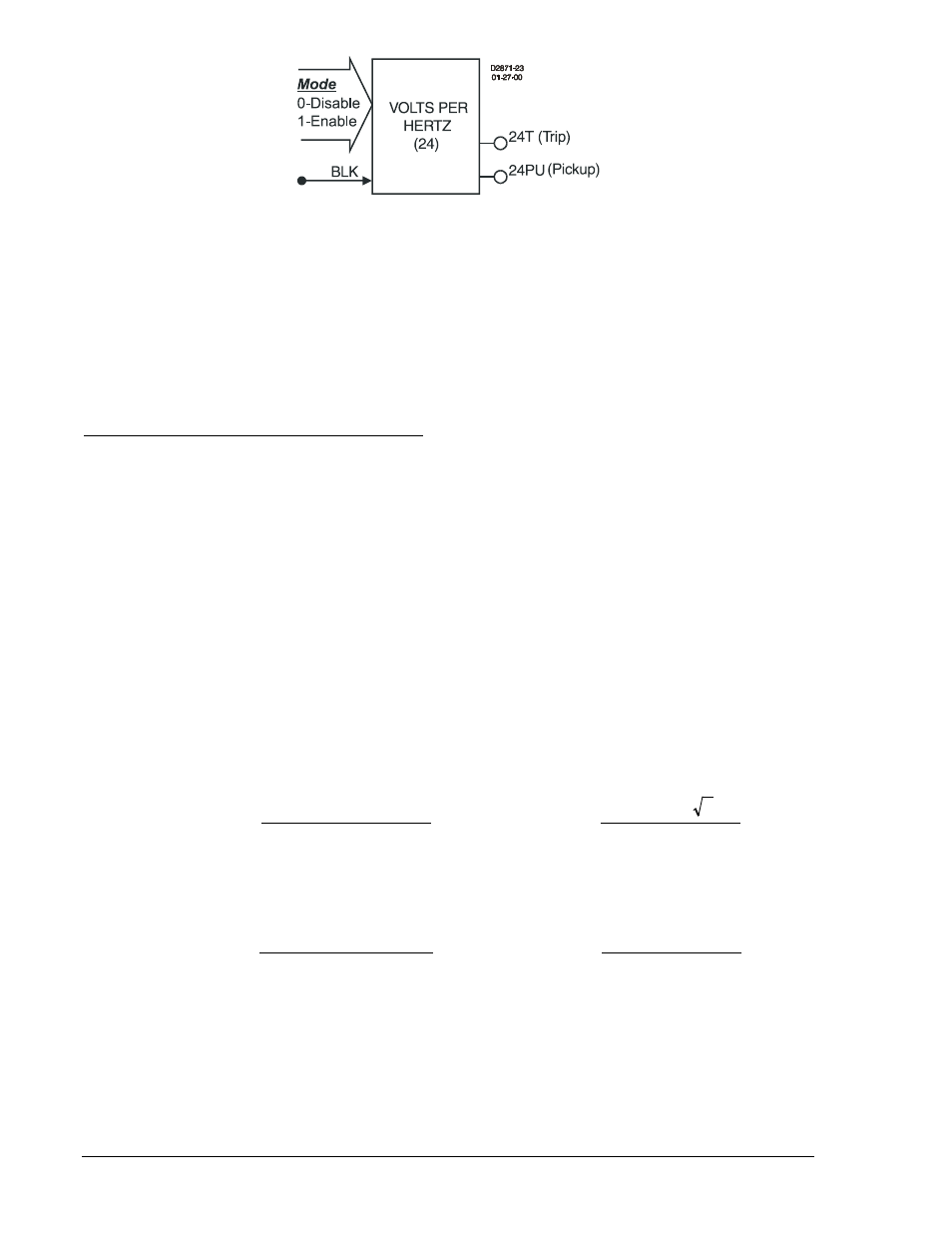
Figure 4-15. Overexcitation Logic Block
The integrating time characteristic closely approximates the heating characteristic of the protected
equipment as overexcitation increases. A linear reset characteristic provides for the decreasing (cooling)
condition.
The 24 element is enabled or disabled by the Mode input. Two modes are available. Selecting Mode 0
disables protection; Mode 1 enables the 24 element.
The BLK (Block) input is used to disable protection. A BESTlogic expression defines how the BLK input
functions. When this expression is TRUE, the element is disabled by forcing the outputs to logic 0 and
resetting the timers. This feature functions in a similar way to the torque control contact of an
electromechanical relay.
Theory of Operation for Overexcitation Protection
V/Hz protection responds to the magnitude of voltage versus frequency where the measured voltage is
phase-phase and includes the phase with the frequency measurement element. If monitored V/Hz is
above a pickup setting, the pickup bit is asserted and integrating and/or definite time timers start timing
towards trip. The trip output becomes TRUE when the first timer times out (integrating or definite time
characteristic). If monitored V/Hz is above both the integrating and definite time pickup thresholds, the
definite time delay has priority over the integrating time characteristic.
The pickup settings determine the V/Hz pickup level. The measured V/Hz is always calculated as the
measured voltage divided by the sensed system frequency. The measured phase depends on the
sensing voltage setting, SG-VTP. The 24 function monitors VAB for both 3-wire and 4-wire connections.
Thus, setting is in VPP/Hz for VT connection = 3W, 4W, AB, BC, CA and VPN/Hz for VT connection =
AN, BN, CN. For more information, refer to Section 3, Input and Output Functions.
Nominal voltage for the BE1-700 is defined as a phase to neutral quantity. (Refer to Section 3, Input and
Output Functions, for details). Nominal V/Hz depends on the sensing voltage (VT) connection, nominal
voltage, and nominal frequency settings. Nominal V/Hz is calculated as the nominal voltage divided by
nominal frequency. For VT connections equal to 3W, 4W, AB, BC, CA, the nominal voltage (phase-neutral
value) must be converted to a phase-phase value by multiplying by the square root of 3. No additional
conversion is required for VT connections equal to AN, BN, or CN.
For 3W, 4W, AB, BC, or CA phase to phase sensing connections:
Frequency
Nominal
3
V
V/Hz
Frequency
Measured
V
Measured
V/Hz
Nominal
Nominal
Phase
-
Phase
Measured
∗
=
=
Equation 4-3. Calculate V/Hz for 3W, 4W, AB, BC, or CA Connections
For AN, BN, or CN phase to neutral sensing connections:
Frequency
Nominal
V
V/Hz
Frequency
Measured
V
Measured
V/Hz
Nominal
Nominal
Neutral
-
Phase
Measured
=
=
Equation 4-4. Calculate V/Hz for AN, BN, or CN Connections
Equations 4-5 and 4-6 represent the trip time and reset time for a constant V/Hz level. Normally, the V/Hz
pickup is set to a value greater than the V/Hz nominal. This ensures that V/Hz measured divided by V/Hz
nominal is always greater than 1.000 throughout the pickup range. If the pickup is set less than nominal,
then measured values above pickup and below nominal will result in the maximum time delay. The
maximum time delay is determined by Equation 4-5 with (V/Hz measured / V/Hz nominal) set equal to
4-20
BE1-700 Protection and Control
9376700990 Rev M