Voltage transformer fuse loss detection (be1-700v), 60fl - fuse loss detection, 60fl - fuse loss detection -60 – Basler Electric BE1-700 User Manual
Page 116: Figure 4-58. 25vm logic -60, Figure 4-59. fuse loss detection logic block -60, Table 4-35. logic settings for voltage monitor -60, Figure 4-58, N table 4-35, N figure 4-58
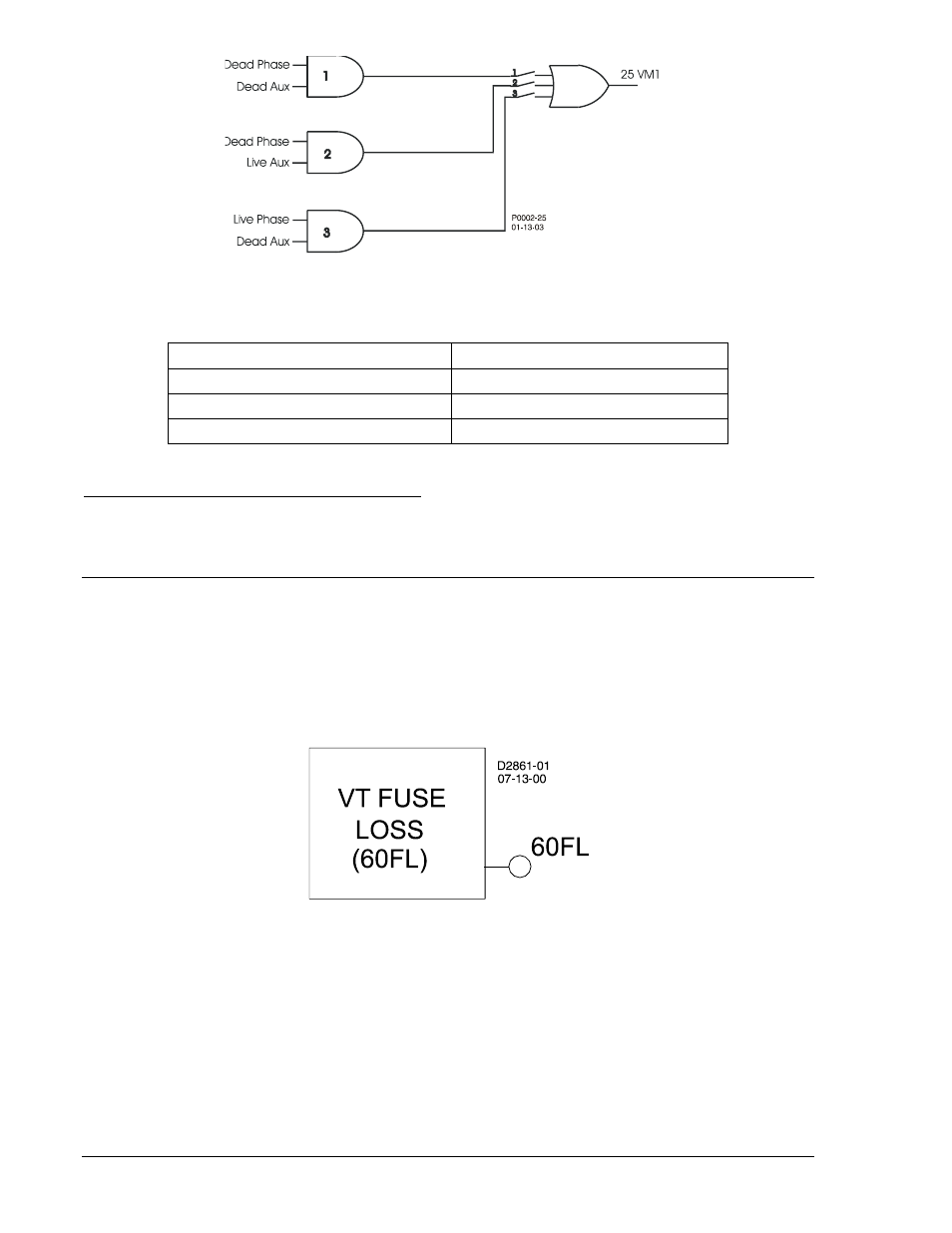
Figure 4-58. 25VM Logic
Table 4-35. Logic Settings for Voltage Monitor
Voltage Monitor Logic Condition
Logic Setting
Dead Phase and Dead Aux
1
Dead Phase and Live Aux
2
Live Phase and Dead Aux
3
Retrieving Voltage Monitor Status from the Relay
The status of each logic variable can be determined through the ASCII command interface using the RG-
STAT (report general-status) command. See Section 6, Reporting and Alarm Functions, General Status
Reporting, for more information. The status can also be determined using BESTCOMS Metering screen.
VOLTAGE TRANSFORMER FUSE LOSS DETECTION (BE1-700V)
60FL - Fuse Loss Detection
BE1-700 relays have one 60FL element that can be used to detect fuse loss or loss of potential in a
three-phase system. The 60FL element is illustrated in Figure 4-59. When the element logic becomes
TRUE, the 60FL logic output becomes TRUE. A logic diagram is shown in Figure 4-60. Logic parameters
are shown in Table 4-36.
Figure 4-59. Fuse Loss Detection Logic Block
Trip Logic: 60FL Trip = (A * C * G) (See Table 4-36.)
Reset Logic: 60FL Reset = H * /K (See Table 4-36.)
4-60
BE1-700 Protection and Control
9376700990 Rev M