Figure 4-31. over/under frequency logic block -36 – Basler Electric BE1-700 User Manual
Page 92
(except for the improbable case of a perfect load to generation match) making frequency measurement
an excellent method for detecting an island condition.
Each element has an adjustable frequency (Hz) setpoint and time delay. The 81 elements share a
common undervoltage inhibit setting for under/overfrequency applications. Power system frequency is
measured on the A-phase voltage input for four-wire or single-phase connections or the AB voltage input
when in three-wire mode. Power system frequency is measured on the optional auxiliary voltage input as
well. When the applied voltage is greater than 10 volts, the BE1-700 measures the frequency. The
measured frequency is the average of two cycles of measurement.
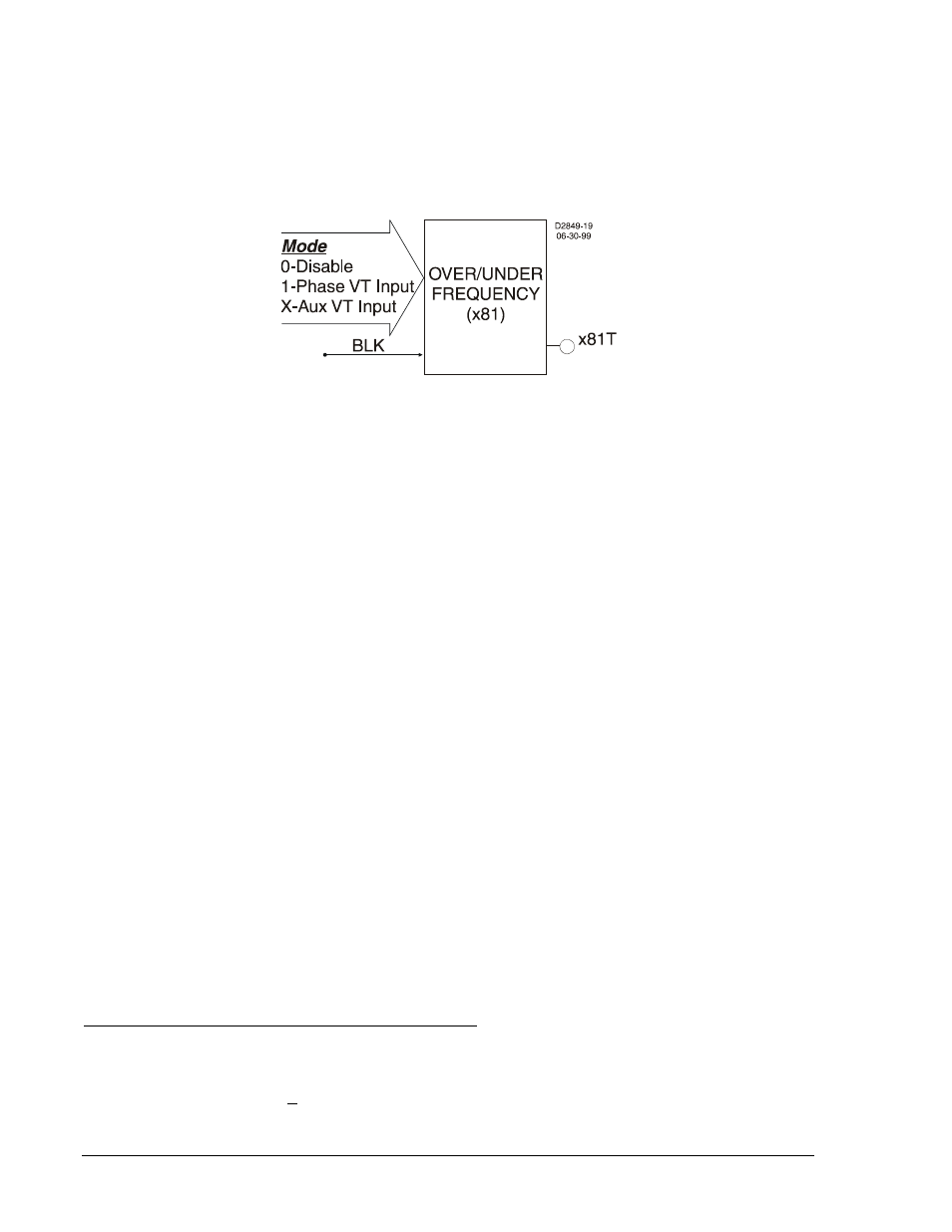
Figure 4-31. Over/Under Frequency Logic Block
Frequency element designations are 81, 181, 281, 381, 481, and 581. Each of the six elements has
identical inputs, outputs, and setting provisions as shown in Figure 4-31. An x81T (trip) output is provided
on each element. For over/under frequency applications, the pickup output becomes TRUE when the
monitored frequency decreases below (81U) or increases above (81O) the pickup setting at which point
the element starts timing toward a trip. The trip output becomes TRUE when the element's time delay
setting has expired. If the pickup bit drops out before the timer expires, it resets and will start over on the
next pickup.
The BLK (Block) input is used to disable protection. A BESTlogic expression is used to define how the
BLK input functions. When this expression is TRUE, the element is disabled by forcing the outputs to logic
0 and resetting the timer. This feature functions in a similar way to the torque control contact of an
electromechanical relay.
An element is enabled or disabled by the Mode input. Three mode options are possible. Mode 0 disables
protection, Mode 1 enables the element to monitor the frequency on the VTP input, and mode X enables
the element to monitor the frequency on the VTX input. Security of your load-shedding scheme can be
enhanced by monitoring two independent VT circuits. See Section 8, Application, Application Tips, for
more information. More information about logic mode selections is provided in the following BESTlogic
Settings for Under/Over Frequency paragraphs.
Pickup settings define the frequency setpoint and time delay, and program the element for under/over
frequency protection. The setpoint defines the value of frequency that will initiate action by an element.
The time delay setting determines how long it takes for the trip output to become TRUE once the
measured frequency reaches the setpoint. If three consecutive cycles of the measured frequency have
decreased below or increased above and the timer has timed out, the 81T will trip. If the timer has not
timed out and the frequency remains in the pickup range for the remainder of the time delay, the 81T will
also trip. If the monitored voltage decreases below the user-defined setpoint, over/under frequency
protection is inhibited.
If the target is enabled for the element, the target reporting function will record a target for the appropriate
element (x81) when the protective function trip output is TRUE and the fault recording function trip logic
expression is TRUE. The target displayed on the HMI will be 81, 181, etc. Element settings determine if
the x81 target is the result of an over or under operation. See Section 6, Reporting and Alarm Functions,
Fault Reporting, for more information about target reporting.
BESTlogic Settings for Over/Under Frequency Protection
BESTlogic settings are made from the BESTlogic Function Element screen in BESTCOMS. Figure 4-32
illustrates the BESTCOMS screen used to select BESTlogic settings for the Over/Under Frequency
element. To open the BESTlogic Function Element screen for Over/Under Frequency element, select
Voltage Protection from the Screens pull-down menu and select the INH/81/181/281/381/481/581 tab.
Then select the BESTlogic button for the element to be programmed. Alternately, settings may be made
using the SL-<x>81 ASCII command.
4-36
BE1-700 Protection and Control
9376700990 Rev M