Figure 4-45. logic timers screen -47 – Basler Electric BE1-700 User Manual
Page 103
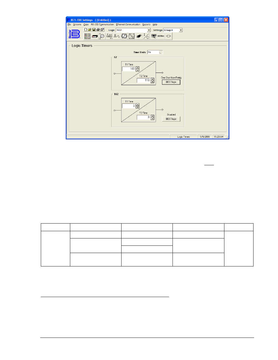
Figure 4-45. Logic Timers Screen
At the top left of the screen is a pull-down menu labeled Logic. This menu allows viewing of the
BESTlogic settings for each preprogrammed logic scheme. User or custom logic must be selected on this
menu in order to allow changes to be made to the mode and inputs of the element.
Beneath the Logic pull-down menu is a pull-down menu labeled Settings. The Settings menu is used to
select the setting group that the element's settings apply to. See Section 7, BESTlogic Programmable
Logic, Logic Schemes.
Using the pull-down menus and buttons, make the application appropriate settings to the Logic Timers
element.
Table 4-28 summarizes the operating settings for General Purpose Logic Timers.
Table 4-28. Operating Settings for General Purpose Logic Timers
Setting
Range
Increment
Unit of Measure
Default
T1 Time,
T2 Time
0 to 999 ms
1
Milliseconds
0
0.1 to 9999 sec.
0.1 for 0.1 to 9.9 sec.
Seconds
1.0 for 10 to 9999 sec.
0 to 599,940 (60 Hz)
0 to 499,950 (50Hz)
∗
Cycles
∗ Time delays less than 10 cycles can be entered to the nearest 0.1 cycles through the HMI. All time
delays can be entered to the nearest 0.01 cycles from the ASCII command interface. Time delays entered
in cycles are converted to milliseconds or seconds. Increment precision after conversion is limited to that
appropriate for each of those units of measure.
Retrieving General Purpose Logic Timers Status from the Relay
The status of each logic variable can be determined from the ASCII command interface by using the RG-
STAT (report general-status) or the RL (report logic) commands. Status can also be determined using
BESTCOMS Metering screen. See Section 6, Reporting and Alarm Functions, General Status Reporting,
for more information.
9376700990 Rev M
BE1-700 Protection and Control
4-47