Overcurrent protection (be1-700c), Overcurrent protection (be1-700c) -9 – Basler Electric BE1-700 User Manual
Page 65
OVERCURRENT PROTECTION (BE1-700C)
The BE1-700C includes instantaneous elements for Phase, Neutral or Ground, and Negative-Sequence
as well as time overcurrent elements for Phase, Neutral or Ground, and Negative-Sequence.
50T - Instantaneous Overcurrent Protection with Settable Time Delay
There are two BESTlogic elements for phase (50TP and 150TP), two elements for ground (50TN and
150TN), and two elements for negative-sequence (50TQ and 150TQ) instantaneous overcurrent
protection. The alphanumeric designation for each element contains the letter T to indicate that the
element has an adjustable time delay. If an element has a time delay setting of zero, then that element
will operate as an instantaneous overcurrent relay.
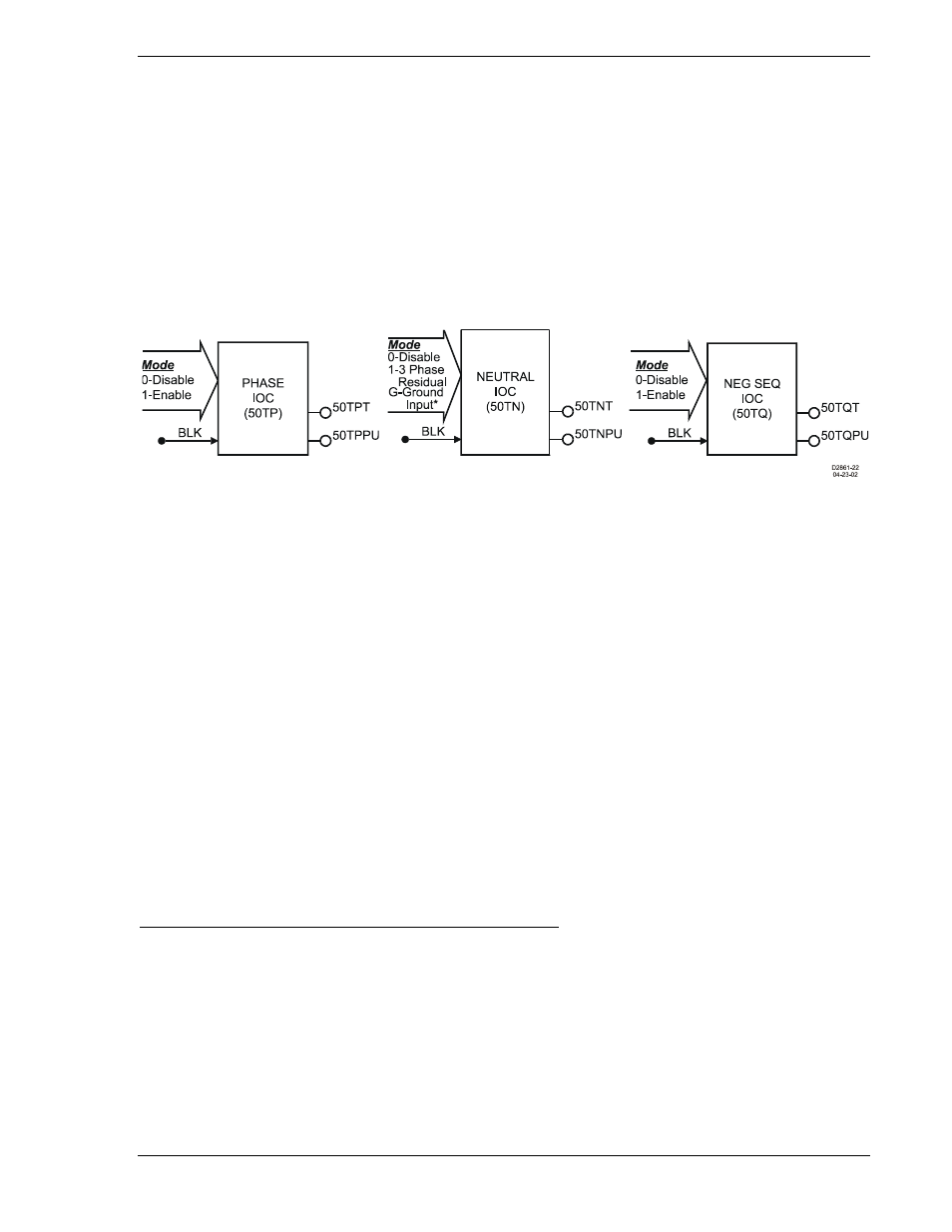
The 50TP, 50TN, and 50TQ instantaneous overcurrent elements are shown in Figure 4-6. The 150TP,
150TN, and 150TQ elements are identical to their counterparts. Each element has two logic outputs:
Pickup (PU) and Trip (T).
Figure 4-6. Instantaneous Overcurrent Logic Blocks
Each element has a BLK (Block) input that can be used to disable the function. A BESTlogic expression is
used to define the BLK input. When this expression is TRUE, the element is disabled by forcing the
outputs to logic zero and resetting the timers to zero. This feature functions in a similar way to a torque
control contact of an electromechanical relay.
A Logic Mode input allows each instantaneous overcurrent element to be enabled or disabled. The
ground elements, 50TN, and 150TN can be enabled to operate on calculated 3-phase Residual (3IO),
Mode 1; or on measured ground current through the Ground Input, Mode G. See Mode selections in
Figure 4-6. More information about logic mode selections is provided in the following BESTlogic Settings
for Instantaneous Overcurrent subsection.
Each instantaneous overcurrent function has a pickup and time delay setting. When the measured current
increases above the pickup threshold, the pickup output (PU) becomes TRUE and the timer starts. If the
current stays above pickup for the duration of the time delay setting, the trip output (T) becomes TRUE. If
the current decreases below the dropout ratio, which is 95 percent, the timer is reset to zero.
The phase overcurrent protective functions include three independent comparators and timers, one for
each phase. When current increases above the pickup setting, the pickup output asserts. If the trip
condition is TRUE for any one phase, the trip logic output asserts.
If the target is enabled for the element, the target reporting function will record a target for the appropriate
phase when the protective function trip output is TRUE and the fault recording function trip logic
expression is TRUE. See Section 6, Reporting and Alarm Functions, Fault Reporting, for more
information about target reporting.
BESTlogic Settings for Instantaneous Overcurrent Protection
BESTlogic settings are made from the BESTlogic Function Element screen in BESTCOMS. Figure 4-7
illustrates the BESTCOMS screen used to select BESTlogic settings for the 50T and 150T elements. To
open the BESTlogic Function Element screen, select Overcurrent Protection from the Screens pull-down
menu. Then select the 50T or 150T Tab. Open the BESTlogic Function Element screen for the desired
element by selecting the BESTlogic button corresponding with the desired element. Alternately, these
settings can be made using the SL-50T and SL-150T ASCII commands.
9376700990 Rev M
BE1-700 Protection and Control
4-9