Virtual breaker control switch (101), Virtual breaker control switch (101) -45, Table 13-78. x43 mode 3 pulse commands -45 – Basler Electric BE1-700 User Manual
Page 341
Step 2: Prepare to monitor the virtual switch operation. An ohmmeter or continuity tester may be used
to monitor the contact status of OUT1.
Step 3: Transmit the commands in Table 13-78 to the relay. These commands pulse the 143 Switch On
and Off once. Result: OUT1 contact closes for 200 milliseconds and returns to the open state.
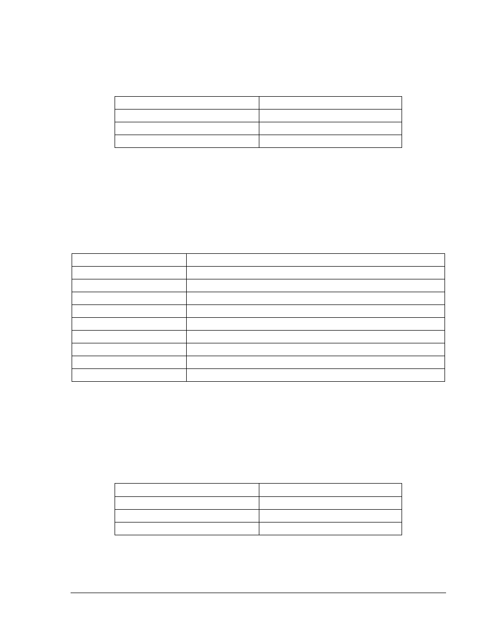
Table 13-78. x43 Mode 3 Pulse Commands
Command
Purpose
A=
Gains write access.
CS-143=P
Selects 143 for Pulse operation.
CO-143=P
Executes 143 for Pulse operation.
Virtual Breaker Control Switch (101)
Purpose: To verify 101 Virtual Breaker Control Switch operation.
Reference Commands: SL-101, CS/CO-101C, CS/CO-101T
Step 1: Prepare the 101 Virtual Breaker Control Switch for testing by transmitting the commands in
Table 13-79 to the relay.
Table 13-79. 101 Virtual Breaker Control Switch Test Commands
Command
Purpose
A=
Gains write access.
SL-N=NONE
Zero out custom logic settings. Overwrite with LOGIC=NONE settings.
Y
Confirm overwrite.
SL-N=S101
Sets S101 as custom logic name.
SL-101=1
Enables 101 Switch.
SL-VO1=101T
Enables OUT1 to close when 101T is TRUE.
SL-VO2=101C
Enables OUT2 to close when 101C is TRUE.
SL-VO3=101SC
Enables OUT3 to close when 101SC is TRUE.
EXIT;Y
Exit and save settings.
Step 2: Prepare to monitor the 101 Virtual Breaker Control Switch operation. Operation can be verified
by monitoring the programmed output contacts, HMI Screen 2.2.1 or by using RG-STAT
command. See Section 6, Reporting and Alarm Functions, for more information.
Step 3: Transmit the commands in Table 13-80 to the relay. These commands place the 101 Switch in
the trip position. Result: OUT1 closes for 200 milliseconds and returns to the open state. OUT3
opens (trip state) and remains open.
Table 13-80. 101 Virtual Breaker Control Switch Trip Test Commands
Command
Purpose
A=
Gains write access.
CS-101T=T
Selects 101T for Trip operation.
CO-101T=T
Executes 101T for Trip operation.
Step 4: Transmit the commands in Table 13-81 to the relay. These commands place the 101 Switch in
the closed state. Result: OUT2 closes for 200 milliseconds and returns to the open state. OUT3
closes (close state) and remains closed.
9376700990 Rev M
BE1-700 Testing and Maintenance
13-45