Basler Electric BE1-700 User Manual
Page 350
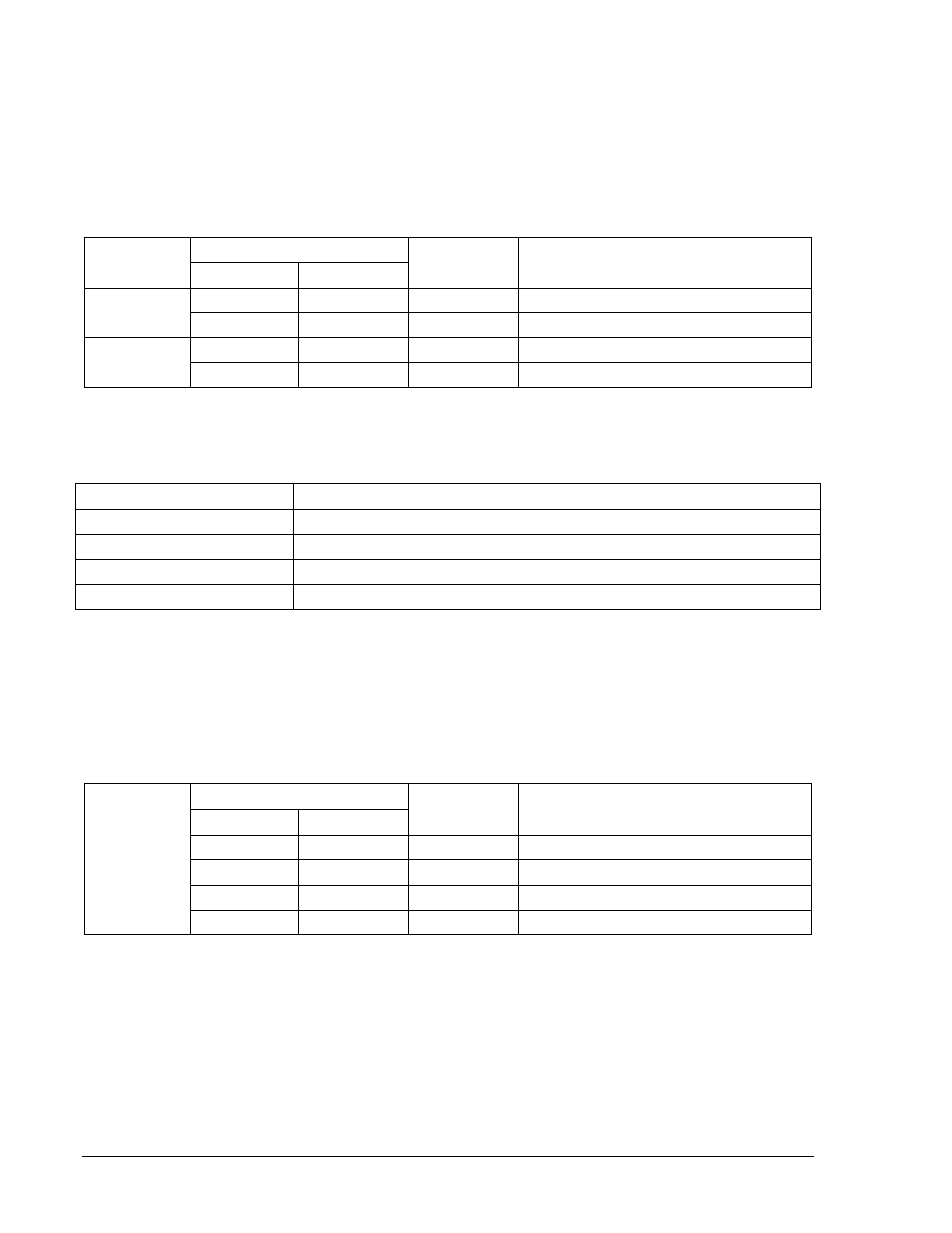
Step 5: Using the values listed in Table 13-96, apply current to the A-phase current input. Begin at the
starting point and then step the current up to just slightly above the low limit for the amount of
time listed. If the active setting group does not change, step the current up to just below the high
limit for the duration indicated. The setting group should change should occur between the low
and high limits. Verify that the change occurred within the time limits programmed at an
accuracy of
±5 percent or ±2 seconds, whichever is greater. Step the current up to each new
level and verify the setting group change and pickup accuracy.
Table 13-96. Setting Group Change Example Accuracy Limits – Increasing Current
Sensing
Type
Current Limit
Time
Comments
Low
High
1 A
0.5
0.5
Starting point 50% pickup.
0.735
0.765
> 1 min
Switch to SG1 (75% SG0 51P).
5 A
2.5
2.5
Starting point 50% pickup.
3.675
3.825
> 1 min
Switch to SG1 (75% SG0 51P).
Step 6: Transmit the select and operate commands in Table 13-97 to the relay.
Table 13-97. Automatic Setting Group Control Selection
Command
Purpose
A=
Gains write access.
CS-143=1
Selects 143 for TRUE operation.
CO-143=1
Executes 143 TRUE operation.
EXIT
Exit select and operate mode.
Step 7: Begin stepping down the current from one level to the next as shown in Table 13-98. First, step
the current down to just below the high limit for the amount of time listed. If the active setting
group does not change, step the current down to just above the low limit for the duration
indicated. This will verify the accuracy of the pickup. Continue stepping the current down to
each new level.
Table 13-98. Setting Group Change Example Accuracy Limits – Decreasing Current
Sensing
Type
Current Limit
Time
Comments
Low
High
0.867
0.833
> 1 min
Switch to SG1 (85% SG0 51P).
0.714
0.686
> 1 min
Switch to SG0 (70% SG0 51P).
4.335
4.165
> 1 min
Switch to SG1 (85% SG0 51P).
3.57
3.43
> 1 min
Switch to SG0 (70% SG0 51P).
Step 8: Remove the current from Phase A, Terminals D1 and D2.
Step 9: Using the RS-LGC command to retrieve logic variable data from the SER, verify that the
following actions were logged:
• Verify that all setting group changes were logged.
• Verify that VO1 went TRUE and closed relay output OUT1 when SG1 became the active
setting group.
• Verify the events that occurred in reverse order when the current was being stepped down.
13-54
BE1-700 Testing and Maintenance
9376700990 Rev M