Settings example for overexcitation protection -24, Figure 4-18. time shown on vertical axis -24, Figure 4-19. time shown on horizontal axis -24 – Basler Electric BE1-700 User Manual
Page 80
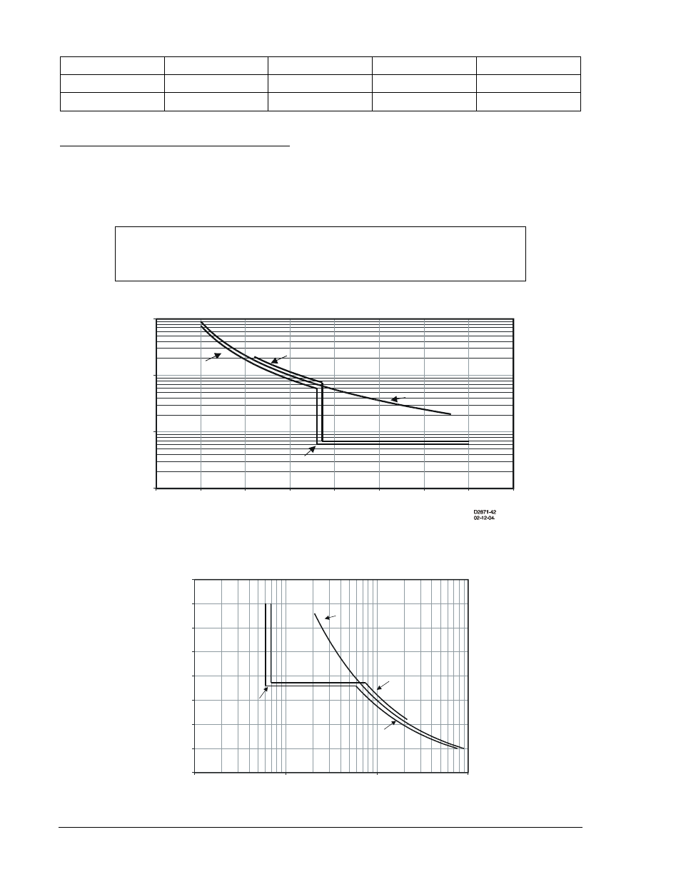
Table 4-15. Programmable Alarm Settings for Overexcitation Protection
Setting
Range
Increment
Unit of Measure
Default
Alarm Level
0.5 - 6
0.1
Sec. V/Hz
0
Alarm Time Delay
0.050 – 600
3 digit resolution
Seconds
0
Settings Example for Overexcitation Protection
V/Hz tripping elements are used to de-energize a generator or transformer that is experiencing an
overexcitation condition. Therefore, the manufacturer's overexcitation limit curves are required to
establish optimum protection. Figure 4-18 and Figure 4-19 show examples of a transformer and generator
limit curve along with the optimum composite protection characteristic.
Figure 4-18. Time Shown on Vertical Axis
Figure 4-19. Time Shown on Horizontal Axis
Volt/Hz Characteristic
1.0
10.0
100.0
1000.0
100%
105%
110%
115%
120%
125%
130%
135%
140%
Percent of Nominal V/Hz
T
im
e
in
S
e
c
o
n
d
s
Transformer Limit
Generator Limit
Inverse
105%, TD=1.9
Definite
118%, 6s
Volt/Hz Characteristic
100%
105%
110%
115%
120%
125%
130%
135%
140%
1.0
10.0
100.0
1000.0
Time in Seconds
P
e
rc
e
n
t
o
f
N
o
m
in
a
l
V
/H
z
Transformer Limit
Generator Limit
Inverse
105%, TD=1.9
Definite
118%, 6s
D2871-43
02-12-04
NOTE
Actual damage curves must be obtained from the equipment manufacturer for
particular equipment to be protected.
4-24
BE1-700 Protection and Control
9376700990 Rev M