Function block logic settings, Output logic settings, Function block logic settings -6 – Basler Electric BE1-700 User Manual
Page 174: Output logic settings -6, Figure 7-4. recloser element -6, Figure 7-5. virtual output logic -6
Function Block Logic Settings
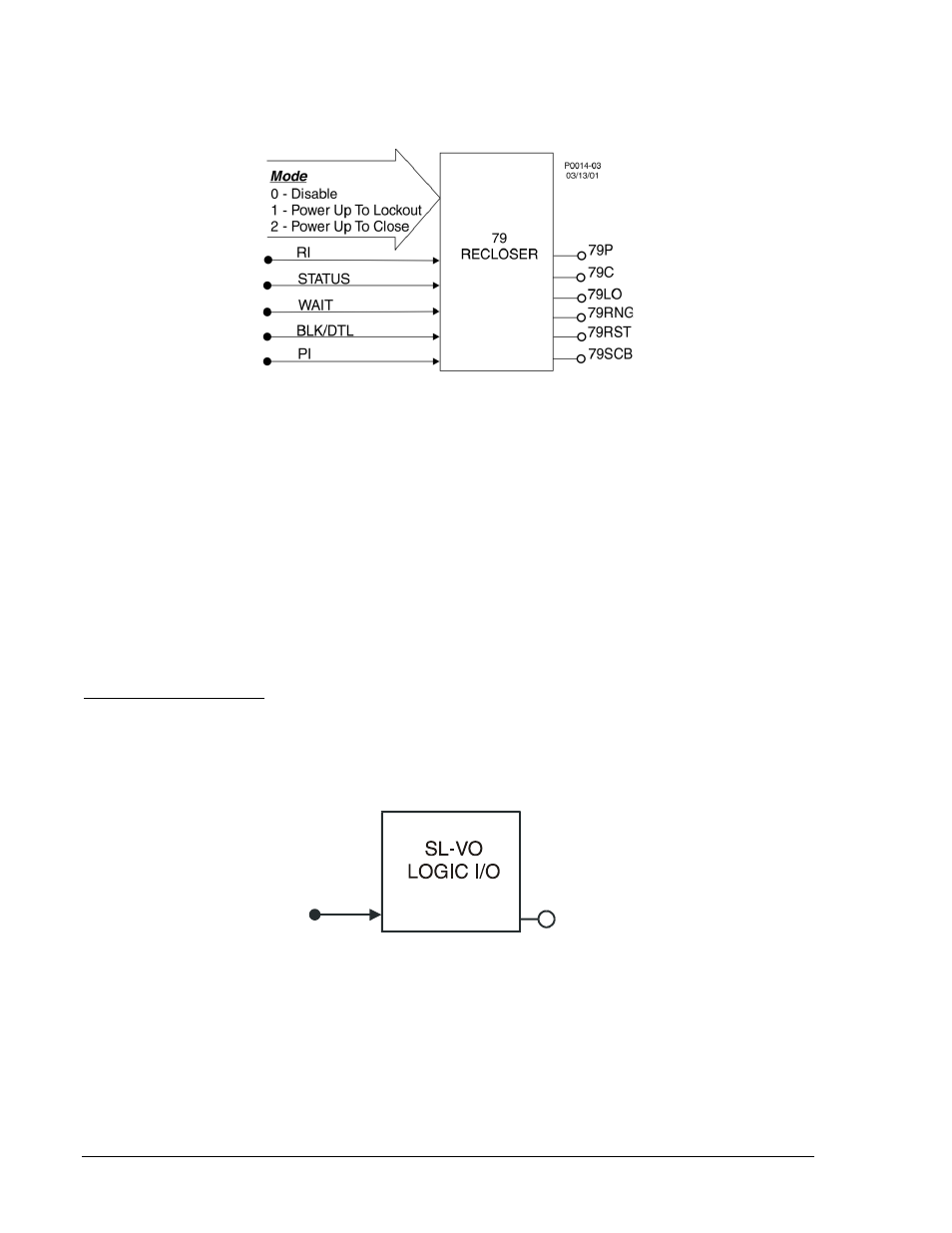
Each BESTlogic function block is equivalent to its discrete device counterpart. For example, the Recloser
Logic Function Block of Figure 7-4 has many of the characteristics of a BE1-79M Multiple Shot Reclosing
Relay.
Figure 7-4. Recloser Element
Before using a protection or control function block, two items must be set: the Mode and the Input Logic.
Setting the Mode is equivalent to deciding which protection or control functions will be used in a logic
scheme. The Input Logic establishes control of a function block.
Mode and input logic information is contained in logic setting command strings. Depending on the
command, the mode setting can either enable or disable a logic input or determine how a function block
operates. Input logic defines which logic variables control or disable a logic function. An example of an
input logic equation is SL-181=1,IN3+VO6. In this frequency logic command string, the 1 parameter
indicates that the 181 function is enabled. The IN3+VO6 expression indicates that the 181 function is
disabled when input 3 or virtual output 6 is TRUE.
The AND operator may not be applied to the terms of an input logic equation. Any number of variables or
their inverse can be combined in a function block input logic expression. Section 4, Protection and
Control, provides detailed information about setting the logic for each function block.
Output Logic Settings
Defining Output Operation
Output operation is defined by Boolean logic equations. Each variable in an equation corresponds to the
current state (evaluated every quarter cycle) of an input, output, or timer. Figure 7-5 illustrates this
relationship. Every quarter cycle, output expressions are evaluated as TRUE or FALSE. If a logic output
that corresponds to a hardware output changes state, then the corresponding output relay contact also
changes state.
Figure 7-5. Virtual Output Logic
When the relay is powered up, all logic outputs are disabled and most variables (including virtual outputs)
initialize as FALSE. Some variable states are stored in EEPROM and are restored to the last state prior to
loss of power. These variables include 43/143,101SC, SG0, and SG1. All control commands, including
logic override control, are also stored in EEPROM. If you override output logic and force an output to
open, that condition will be maintained even if operating power is cycled.
When the logic is running and logic expression SL-VO[n] is FALSE, then output VO[n] = 0. When the logic
is running and logic expression SL-VO[n] is TRUE, then VO[n] = 1. Hardware outputs OUTA and OUT1
through OUT5 follow the corresponding logic outputs VOA and VO1 through VO5.
VO[n]
LOGIC
EQUATION
D2861-16
08-21-03
7-6
BE1-700 BESTlogic Programmable Logic
9376700990 Rev M