Mode 6, latch -45, Figure 4-42. mode 5, integrating timer -45, Figure 4-43. mode 6, latch -45 – Basler Electric BE1-700 User Manual
Page 101
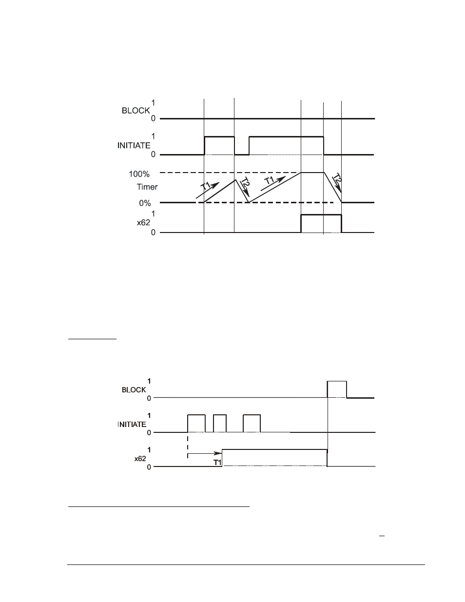
In the example shown in Figure 4-42, RESET time T2 is set to half of the PICKUP time T1 setting. The
initiate input expression becomes TRUE and the timer starts integrating toward pickup. Prior to timing out,
the initiate expression toggles to FALSE and the timer starts resetting at twice the rate as it was
integrating toward time out. It stays FALSE long enough for the integrating timer to reset completely but
then toggles back to TRUE and stays TRUE for the entire duration of time T1. At that point, the output of
the timer is toggled to TRUE. Then at some time later, the initiate expression becomes FALSE and stays
FALSE for the duration of RESET time T2. At that point, the output of the timer is toggled to FALSE.
Figure 4-42. Mode 5, Integrating Timer
This type of timer is useful in applications where a monitored signal may be hovering at its threshold
between on and off. For example, it is desired to take some action when current is above a certain level
for a certain period of time. A 50T function could be used to monitor the current level. Thus, if the current
level is near the threshold so that the INITIATE input toggles between TRUE and FALSE from time to
time, the function will still time out as long as the time that it is TRUE is longer than the time that it is
FALSE. With a simple pickup/dropout timer, the timing function would reset to zero and start over each
time the initiate expression became FALSE.
Mode 6, Latch
A one shot timer starts its timing sequence when the INITIATE input expression changes from FALSE to
TRUE. The timer will time for DELAY time T1 and then the output will latch TRUE. Additional INITIATE
input expression changes of state are ignored. Time (T2) is ignored. Refer to Figure 4-43.
Figure 4-43. Mode 6, Latch
BESTlogic Settings for General Purpose Logic Timers
BESTlogic settings are made from the BESTlogic Function Element screen in BESTCOMS. Figure 4-44
illustrates the BESTCOMS screen used to select BESTlogic settings for the Logic Timer elements. To
open the BESTlogic Function Element screen for Logic Timer, select Logic Timers from the Screens pull-
down menu. Then select the BESTlogic button for either the 62 or the 162 element. Alternately, settings
may be made using the SL-x62 ASCII command.
D2843-12
10-23-03
D2863-07
10-23-03
9376700990 Rev M
BE1-700 Protection and Control
4-45