Zone-sequence coordination, Zone-sequence coordination -53, Figure 4-51 – Basler Electric BE1-700 User Manual
Page 109: Figure 4-52
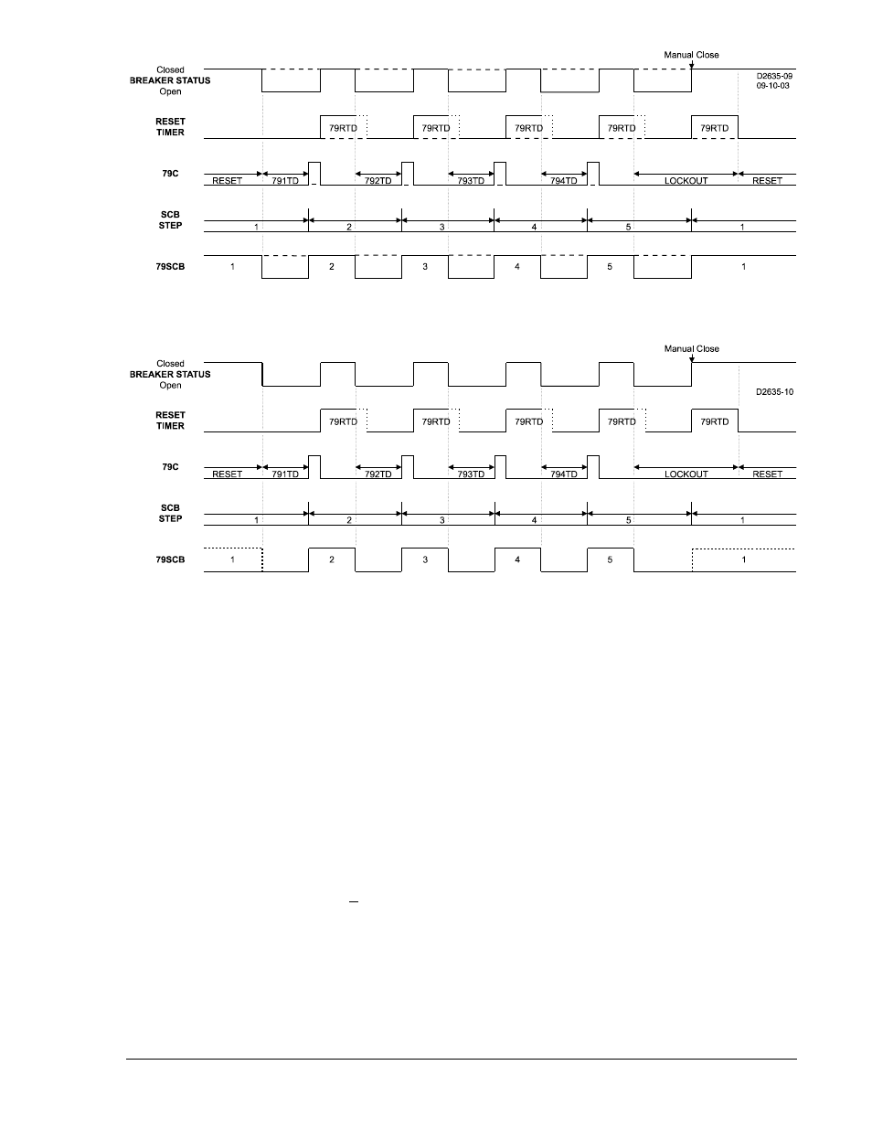
Figure 4-51. S#-79SCB=1/2/3/4/5 Logic Timing Diagram
Figure 4-52. S#-79SCB=2/3/4/5 Logic Timing Diagram
Zone-Sequence Coordination
To coordinate tripping and reclosing sequences with downstream protective relays and reclosers, the
BE1-700 senses fault current from downstream faults when a user programmable logic, set by the SP-
79ZONE command, picks up and then drops out without a trip output (defined with the SG-TRIGGER
command) occurring. Typically, the low-set instantaneous pickup outputs (50TPPU and 50TNPU) or the
time overcurrent pickup outputs (51PPU and 51NPU) are used for the zone sequence settings (SP-
79ZONE=50TPPU+50TNPU or SP79ZONE=51PPU+51NPU).
If the upstream relay (BE1-700) senses that a downstream device has interrupted fault current, the BE1-
700 will increment the trip/reclose sequence by one operation. This occurs because the BE1-700
recognizes that a non-blocked low set (50TP or 50TN) element picked up and reset before timing out to
trip.
BESTlogic settings are made from the BESTlogic Function Element screen in BESTCOMS. Figure 4-53
illustrates the BESTCOMS screen used to select Zone Sequence Coordination Logic settings for the
reclosing element. To open the BESTlogic Function Element screen for Reclosing (Zone Sequence
Logic), select Reclosing from the Screens pull-down menu and click on the Logic button next to Zone
Sequence Logic in the lower right corner of the screen. Alternately, settings may be made using the SP-
79ZONE ASCII command.
9376700990 Rev M
BE1-700 Protection and Control
4-53