Breaker failure protection (be1-700c), 50bf - breaker failure protection, Breaker failure protection (be1-700c) -39 – Basler Electric BE1-700 User Manual
Page 95: 50bf - breaker failure protection -39, Figure 4-34. breaker failure logic block -39
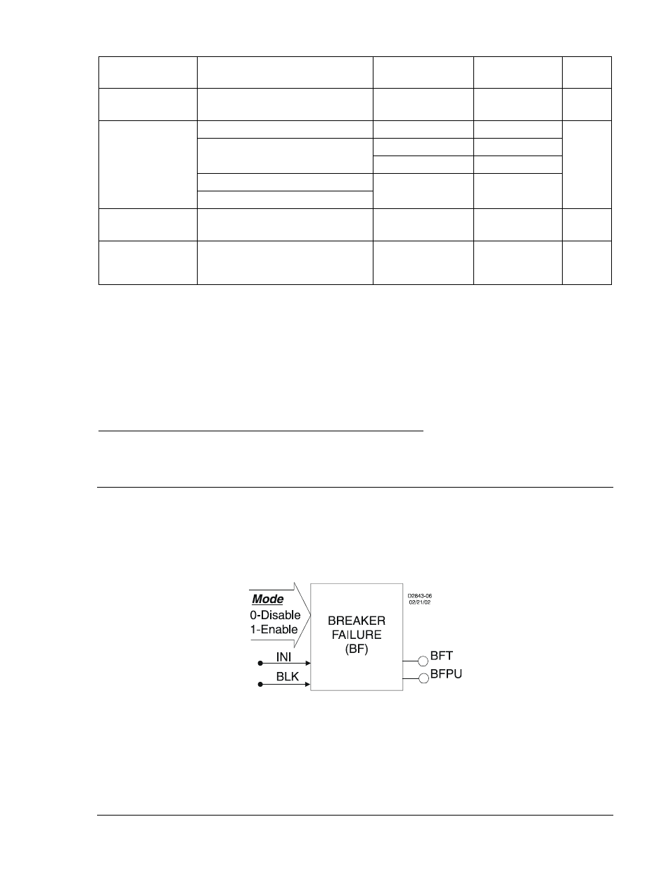
Table 4-24. Operating Settings for Over/Under Frequency Protection
Setting
Range
Increment
Unit of
Measure
Default
81 O/U Pickup
0 = Disabled
20 to 70 Hz
0.01
Hertz
0
Time Delay
0 to 999 Milliseconds
1
Milliseconds
0
0.0 to 600 Seconds
0.1 for 0.1 to 9.9
Seconds
1.0 for 10 to 600
Seconds
3 to 36,000 cycles (60 Hz)
∗
Cycles
2.5 to 30,000 cycles (50 Hz)
Mode
O =
U =
Over
Under
N/A
N/A
1
81 O/U Voltage
Inhibit Level
0 = Disabled
0.1 for 15 to 99.9
1.0 for 100 to 150
Secondary
Volts †
40
15 to 150 Sec. Volts
∗ Time delays less than 10 cycles can be entered to the nearest 0.1 cycles from the front panel HMI. All
time delays can be entered to the nearest 0.01 cycles from the ASCII command interface. Time delays
entered in cycles are converted to milliseconds or seconds. Increment precision after conversion is limited
to that appropriate for each of those units of measure.
† Phase-to-phase and phase-to-neutral settings depend on the VTP and VTX connection settings.
The default unit of measure for the voltage inhibit setting is secondary volts. Primary volt (Pri Volt), per
unit volts (Per U Volts), and percent volts (% Volts) can also be selected as the pickup setting unit of
measure. Over/underfrequency inhibit is in hertz. The unit of measure for the Time setting that represents
the element's time delay defaults to milliseconds. It is also selectable for seconds, minutes, and cycles.
Retrieving Over/Under Frequency Protection Status from the Relay
The status of each logic variable can be determined through the ASCII command interface using the RG-
STAT (report general-status) command. See Section 6, Reporting and Alarm Functions, General Status
Reporting, for more information. The status can also be determined using BESTCOMS Metering screen.
BREAKER FAILURE PROTECTION (BE1-700C)
50BF - Breaker Failure Protection
BE1-700 relays provide one function block for breaker failure protection. This function includes a timer
and a current detector. Figure 4-34 shows the BF function block. The function block has two outputs
BFPU (breaker failure pickup) and BFT (breaker failure trip).
Figure 4-34. Breaker Failure Logic Block
An INI (Initiate) logic input is provided to start the breaker failure timer. When this expression is TRUE and
current is flowing in the phase current input circuits, the breaker failure timer is started. Supervision of the
initiate signal can be designed in BESTlogic. Once the breaker failure timer is started, the initiate signal
does not have to remain TRUE.
A BESTlogic expression defines how the BLK (Block) input functions. When this expression is TRUE, the
element is disabled by forcing the outputs to logic 0 and resetting the timer to zero. For example, this may
9376700990 Rev M
BE1-700 Protection and Control
4-39