Basler Electric BE1-700 User Manual
Page 70
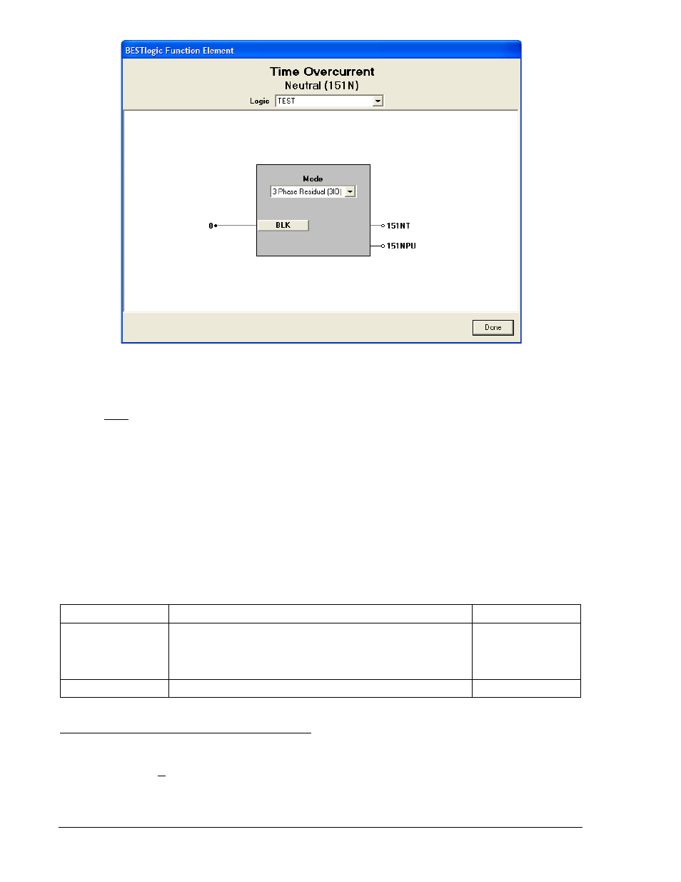
Figure 4-10. BESTlogic Function Element Screen, Neutral (151N)
At the top center of the BESTlogic Function Element screen is a pull-down menu labeled Logic. This
menu allows viewing of the BESTlogic settings for each preprogrammed logic scheme. A custom logic
scheme must be created and selected in the Logic pull-down menu at the top of the screen before
BESTlogic settings can be changed. See Section 7, BESTlogic Programmable Logic.
Enable the Time Overcurrent function by selecting its mode of operation from the Mode pull-down menu.
To connect the functions inputs, select the button for the corresponding input in the BESTlogic Function
Element screen. The BESTlogic Expression Builder screen will open. Select the expression type to be
used. Then, select the BESTlogic variable, or series of variables to be connected to the input. Select
Save when finished to return to the BESTlogic Function Element screen. For more details on the
BESTlogic Expression Builder, see Section 7, BESTlogic Programmable Logic. Select Done when the
settings have been completely edited.
The BESTlogic settings for Time Overcurrent Protection are provided in Table 4-8. These settings enable
an element by attaching it to the CT input circuits and provide blocking control as determined by the logic
expression assigned to the block input.
Table 4-8. BESTlogic Settings for Time Overcurrent Protection
Function
Range/Purpose
Default
Mode
0 = Disabled
1 = Enabled
1 = 3-phase residual (3IO) (51N, 151N only)
G = Ground input (51N, 151N only)
1
BLK
Logic expression that disables function when TRUE.
0
Operating Settings for Time Overcurrent Protection
Operating settings are made using BESTCOMS. Figure 4-11 illustrates the BESTCOMS screen used to
select operational settings for the Time Overcurrent element. To open the screen, select Overcurrent
Protection from the Screens pull-down menu and select either 51 or 151 tab. Alternately, settings may be
made using S<g>-51 and S<g>-151 ASCII commands or from the HMI Screens 5.x.7.1 through 5.x.7.5
where x equals 1 for Setting Group 0 and 2 for Setting Group 1.
4-14
BE1-700 Protection and Control
9376700990 Rev M