Rs-485 connections, Rs-485 connections -20, Figure 12-21. sel-2020 to be1-700 -20 – Basler Electric BE1-700 User Manual
Page 290: Table 12-3. rs-485 pinouts (com2) -20
Advertising
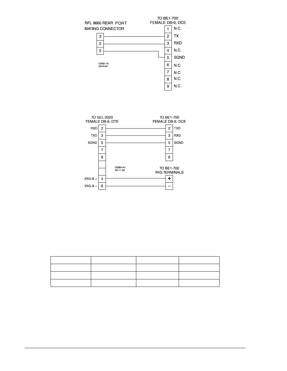
Figure 12-20. RFL9660 Protective Relay Switch to BE1-700 Cable
Figure 12-21. SEL-2020 to BE1-700
RS-485 Connections
RS-485 connections are made at a three-position terminal block connector that mates with a standard
communication cable. A twisted pair cable is recommended. Connector pin numbers, functions, names,
and signal directions are shown in Table 12-3. An RS-485 connection diagram is provided in Figure
12-22.
Table 12-3. RS-485 Pinouts (COM2)
Terminal
Function
Name
Direction
A
Send/Receive A
(SDA/RDA)
In/Out
B
Send/Receive B
(SDB/RDB)
In/Out
C
Signal Ground
(GND)
N/A
12-20
BE1-700 Installation
9376700990 Rev M
Advertising
This manual is related to the following products: