47 - negative-sequence overvoltage protection, 47 - negative-sequence overvoltage protection -33 – Basler Electric BE1-700 User Manual
Page 89
Retrieving Auxiliary Undervoltage/Overvoltage Protection Status from the Relay
The status of each logic variable can be determined through the ASCII command interface using the RG-
STAT (report general-status) command. See Section 6, Reporting and Alarm Functions, General Status
Reporting, for more information. The status can also be determined using BESTCOMS Metering screen.
47 - Negative-Sequence Overvoltage Protection
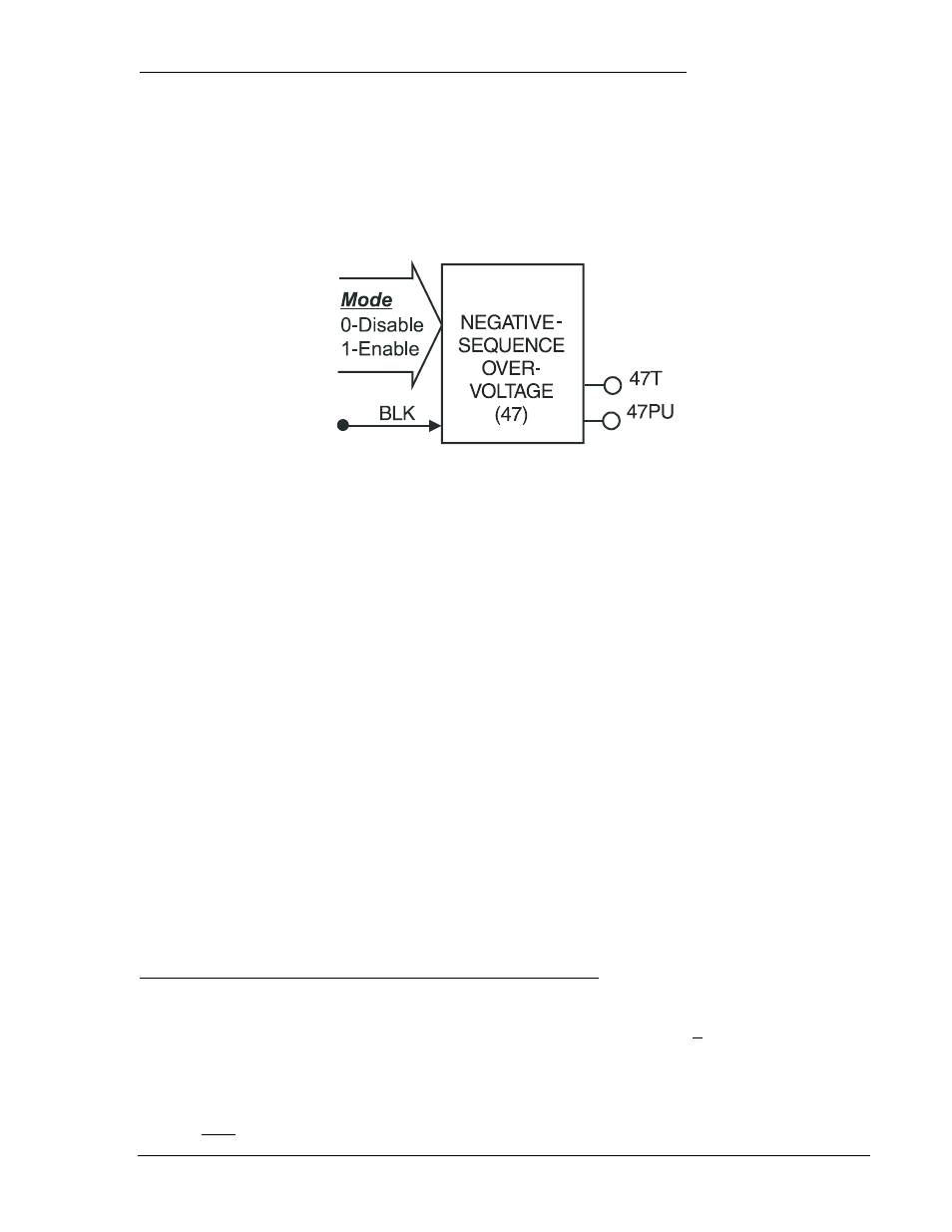
Figure 4-28 illustrates the inputs and outputs of the negative-sequence overvoltage element. Element
operation is described in the following paragraphs. Negative-sequence overvoltage protection is not
available if VTP connection is single-phase.
Figure 4-28. Negative-Sequence Overvoltage Logic Block
The negative-sequence overvoltage element has two outputs: 47PU (pickup) and 47T (trip). When the
monitored negative-sequence voltage increases above the pickup setting, the pickup output becomes
TRUE and the element starts timing toward a trip. The trip output becomes TRUE when the element timer
times out.
The BLK (Block) input is used to disable protection. A BESTlogic expression defines how the BLK input
functions. When this expression is TRUE, the element is disabled by forcing the outputs to logic 0 and
resetting the timer. This feature functions in a similar way to the torque control contact of an
electromechanical relay.
The 47 element is enabled or disabled by the Mode input. Two modes are available. Selecting Mode 0
disables protection. Mode 1 enables the 47 element. More information about logic mode selections is
provided in the BESTlogic Settings for Negative-Sequence Overvoltage paragraphs.
The pickup setting determines the voltage pickup level of the element. Voltage pickup is based on PN.
The time delay setting controls how long it takes for the trip output to become TRUE after the pickup
output becomes TRUE. When the monitored voltage increases above the pickup threshold, the pickup
output (47PU) becomes TRUE and the timer starts. If the voltage remains above the pickup threshold for
the duration of the time delay setting, the trip output (47T) becomes TRUE. If the voltage decreases
below the dropout ratio of 98 percent, the timer is reset to zero.
If the 60FL element trip logic is TRUE and V block is enabled for negative-sequence blocking <Q>, all
functions that use the negative-sequence voltage (V
2
) are blocked. For more information on the 60FL
function, see the paragraphs later in this section.
If the target is enabled for the 47 element, the target reporting function will record a target when the trip
output is TRUE and the fault recording function trip logic expression is TRUE. See Section 6, Reporting
and Alarm Functions, Fault Reporting, for more information about target reporting.
BESTlogic Settings for Negative-Sequence Overvoltage Protection
BESTlogic settings are made from the BESTlogic Function Element screen in BESTCOMS. Figure 4-29
illustrates the BESTCOMS screen used to select BESTlogic settings for the negative-sequence
overvoltage function. To open the screen, select Voltage Protection from the Screens pull-down menu
and then select the 47 Tab. Then select the BESTlogic button at the bottom of the screen. Alternately,
settings may be made using the SL-47 ASCII command.
At the top center of the BESTlogic Function Element screen is a pull-down menu labeled Logic. This
menu allows viewing of the BESTlogic settings for each preprogrammed logic scheme. A custom logic
scheme must be created and selected in the Logic pull-down menu at the top of the screen before
BESTlogic settings can be changed. See Section 7, BESTlogic Programmable Logic.
D2881-29
08-12-04
9376700990 Rev M
BE1-700 Protection and Control
4-33