Table 13-11. 50t and 150t time delay settings -16 – Basler Electric BE1-700 User Manual
Page 312
In addition, the pickup settings made in Step 3 (Table 13-7) must be changed to specify the
setting group being tested. To test settings in Group 1, replace the 0 in the S0-x50 commands
with a 1 (S1-x50).
50TP/150TP and TN (Calculated 3Io) Time Delay Verification
Step 1: Connect a current source to Terminals D1 and D2 (A-phase). Refer to Figure 12-3 for terminal
locations.
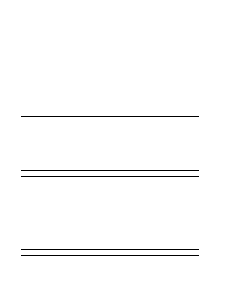
Step 2: Prepare the 50T/150T elements for testing by transmitting the commands in Table 13-10 to the
relay.
Table 13-10. 50TP and 50TN Time Delay Test Commands
Command
Purpose
A=
Gains write access.
SL-N=NONE
Zero out custom logic settings. Overwrite with LOGIC=NONE settings.
Y
Confirm overwrite.
SL-N=TD50
Sets TD50 as custom logic name.
SL-50TP=1,0; SL-50TN=1,0
Enables 50TP and 50TN (3Io), and disables blocking.
SL-VO1=50TPT
Enables OUT1 to close for 50TP trip.
SL-VO2=50TNT
Enables OUT2 to close for 50TN trip.
SG-CT=1
Sets P, N CT ratio at 1:1
SG-TRIG=50TPT+50TNT,
50TPPU+50TNPU,0
Enable 50TPT or 50TNT to log and trigger fault recording.
EXIT;Y
Exit and save settings.
Step 3: Using Table 13-11, transmit the first column of setting commands.
Table 13-11. 50T and 150T Time Delay Settings
Pickup and Time Delay Settings
Purpose
2 Second TD
5 Second TD
10 Second TD
S0-50TP=0.5,2S
S0-50TP=0.5,5S
S0-50TP=0.5,10S
Sets 50TP TD.
S0-50TN=0.5,2S
S0-50TN=0.5,5S
S0-50TN=0.5,10S
Sets 50TN TD.
Step 4: Step the applied A-phase current to .55 amps (for 1 amp CT circuit divide by 5). Measure the
time delay and verify the accuracy of the 50TP time delay setting, OUT1, and 50TN, OUT2.
Timing accuracy is
±5 percent or ±3 cycles of the time delay setting.
Step 5: Repeat Steps 2 and 3 for the middle and higher time delay settings in Table 13-11.
Step 6: (Optional.) Repeat Steps 3 through 5 for phase B (Terminals D3 and D4), phase C (Terminals
D5 and D6).
Step 7: (Optional.) Repeat Steps 1 through 6 for the 150T elements. Overwrite the 50T commands
entered in Step 2 with the commands of Table 13-12.
Table 13-12. 150TP and 150TN Time Delay Test Commands
Command
Purpose
A=
Gains write access.
SL-150TP=1,0; SL-150TN=1,0
Enables 150TP and 150TN, disables blocking.
SL-VO1=150TPT
Enables OUT1 to close for 150TP trip.
SL-VO2=150TNT
Enables OUT2 to close for 150TN trip.
SG-TRIGGER=150TPT+150TNT,
Enable 150TPT or 150TNT to log and trigger fault recording.
13-16
BE1-700 Testing and Maintenance
9376700990 Rev M