Fuse loss detection blocking settings -61, Figure 4-60. 60fl element logic -61, Table 4-36. 60fl logic parameters -61 – Basler Electric BE1-700 User Manual
Page 117: N figure 4-60, Table 4-36, Table 4-36.), E table 4-36.)
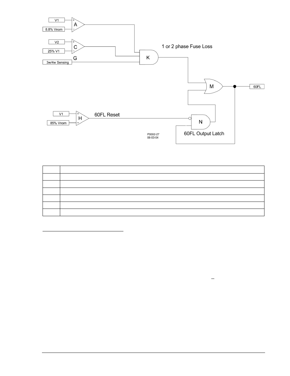
Figure 4-60. 60FL Element Logic
Table 4-36. 60FL Logic Parameters
Input
TRUE Condition
A
Positive-sequence volts greater than 8.8% of the nominal voltage; Detects minimum voltage is applied.
C
Negative-sequence volts greater than 25% of the pos-seq volts; Detects loss of 1 or 2 phase voltages.
G
Three-wire or four-wire sensing selected.
H
Positive-sequence volts greater than 85% of nominal voltage; Detects a restored voltage condition.
K
(A * C * G); Detects when either one or two phases are lost.
M, N
Latches the 60FL output until the reset criteria are met.
Fuse Loss Detection Blocking Settings
The 60FL logic bit is always enabled regardless of the SP-60FL setting. User selectable block settings
determine how certain (not all) current and voltage protective functions operate when a fuse loss
condition exists (see Table 4-37). The I Block setting (51/27R) assumes that the voltage is VNOM when
60FL is TRUE because the voltage measurement is not present or is unreliable. If the input voltage is
nominal, then voltage restraint and control have no effect. The V Block settings (P, N, Q) determine which
voltage functions are blocked when the 60FL logic is TRUE.
Settings are made using BESTCOMS. Figure 4-61 illustrates the BESTCOMS screen used to select
blocking settings for the 60FL element. Select Reporting and Alarms from the Screens pull-down menu
and select the VT Monitor tab. Alternately, settings may be made using the SP-60FL ASCII command.
See Section 11, ASCII Command Interface, Command Summary, Protection Setting Commands, for
more information.
9376700990 Rev M
BE1-700 Protection and Control
4-61