Basler Electric BE1-700 User Manual
Page 216
LCD display automatically goes to the Alarm Screen if VO13 is programmed as a major or minor alarm
per the automatic display priority function. In this example, VO13 is programmed to be SN-
VO13=SPR_TRIP and will display as such on the HMI when an SPR trip occurs. The trip and alarm
(pseudo target) latch will remain until the Reset button on the front panel of the relay is pressed while the
Alarm Screen of the HMI, Menu Branch 1.3 is being displayed (Reset key of the HMI is context sensitive).
Refer to Section 6, Reporting and Alarms Functions, Retrieving and Resetting Alarm Reports, for details.
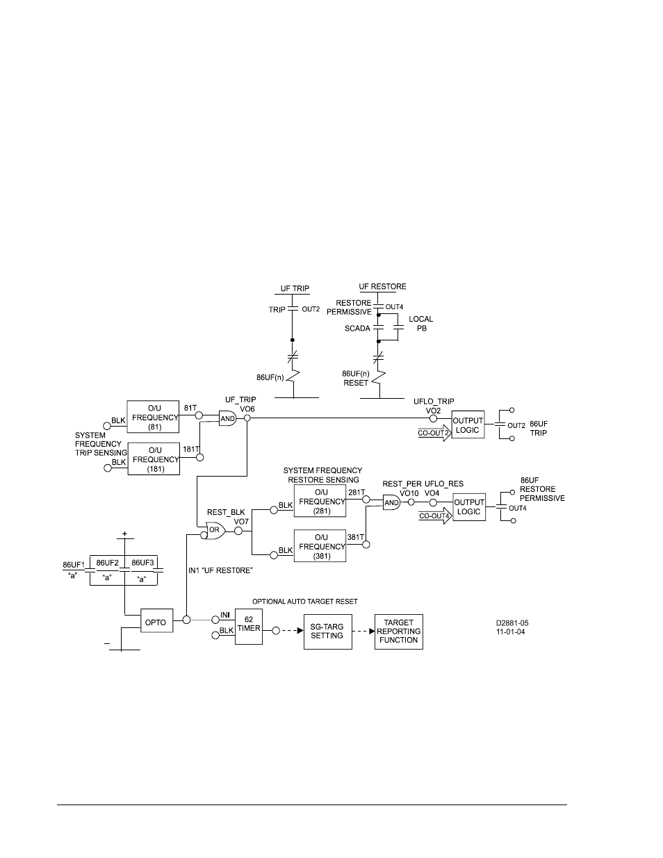
Underfrequency Load Shedding with Restoration Permissive (BE1-700V)
Underfrequency load shedding schemes are designed to operate when the load of a power region
outpaces generation and begins to
Adrag@ or slow system frequency. (See Figure 8-13.) To save the
system from total collapse, segregated blocks of load representing a percentage of the total power region
load are set to trip at various levels of declining system frequency. For example, an electric utility
determines that 30% of its load will have to be shed for a worst case
Aload to generation@ scenario. They
decide to arrange the load in three blocks set to trip at underfrequency levels of 59.7 Hz, 59.5 Hz and
59.3 Hz. Load restoration is normally broken down into smaller blocks minimizing the impact of reapplying
load to the system. Knowledge of local conditions or
Arestoration permissives@ are normally included as
part of the system restoration process.
Figure 8-13. Underfrequency Load Shed Bus Level Application
Historically, underfrequency load shedding schemes have been applied at the bus level. With the
introduction of numeric, multifunction feeder protection relays, it has become more economical to apply
underfrequency load shedding at the circuit level. Also, reliability increases as the user is no longer
depending on a single relay to sense the underfrequency condition. If the BE1-700V is not available on
every circuit or user philosophy requires a bus level installation, the BE1-700V can also be applied for bus
level underfrequency protection.
The BE1-700V also has an optional auxiliary voltage input that can be selected for the underfrequency
function. This allows the user to supply one underfrequency element from a transmission or high side
8-34
BE1-700 Application
9376700990 Rev M