Alarms, Alarms -17 – Basler Electric BE1-700 User Manual
Page 199
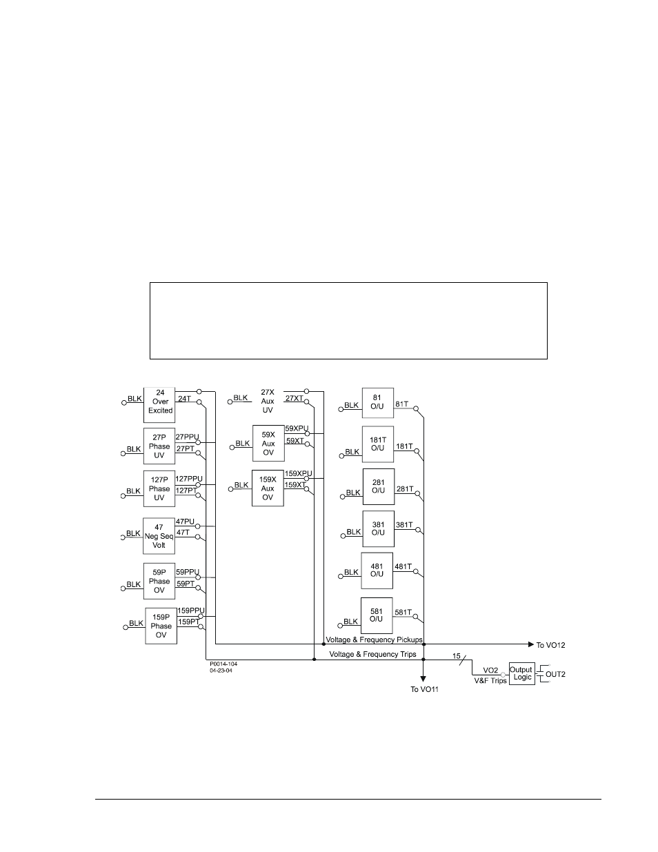
To ensure optimum flexibility for voltage and frequency applications, two over/undervoltage elements
(59P-159P/27P-127P), one phase sequence check (negative-sequence voltage (47)), six over/under
frequency elements (81o/u
Y581o/u) and one volts/hertz element (24) are provided.
Integration of Protection, Control and I/O Elements
Table 8-15 includes the logic equations that connect the various elements (electronic wiring) of the
voltage protection scheme. Figures 8-5 and 8-6 (sheets 1& 2) show the logic drawings for the
preprogrammed protection scheme. Note that all voltage and frequency trips are connected to VO8 and to
VO2 which, in turn, operates Output 2. Input 1 provides breaker position/status to the logic scheme.
Alarms
Three logic variables drive the front panel LEDs: Relay Trouble (ALMREL), Major Alarm (ALMMAJ) and
Minor Alarm (ALMMIN). A fourth logic variable, Logic Alarm (ALMLGC), has no associated front panel
LED. When the relay self-test detects a problem in the relay (ALMREL) as programmed for the OC & V
protection scheme, the Relay Trouble LED lights, Output A operates and all other outputs are disabled.
When a major or minor alarm is detected, the associated LED lights. If the user chooses, Output A can
also be set to operate for a major or a minor alarm.
Figure 8-5. 700V-OUVF-A-BE (Over/Under V & F Protection) Logic Diagram (1 of 2)
NOTE
Tables 8-11 through Table 8-14 provide detailed logic definitions for the inputs,
outputs, protection and control elements. All inputs, logic blocks, and outputs
available for use in the preprogrammed logic are described in the following
tables.
9376700990 Rev M
BE1-700 Application
8-17