Negative-sequence coordination settings -18, Figure 4-14. phase-to-phase fault magnitude -18 – Basler Electric BE1-700 User Manual
Page 74
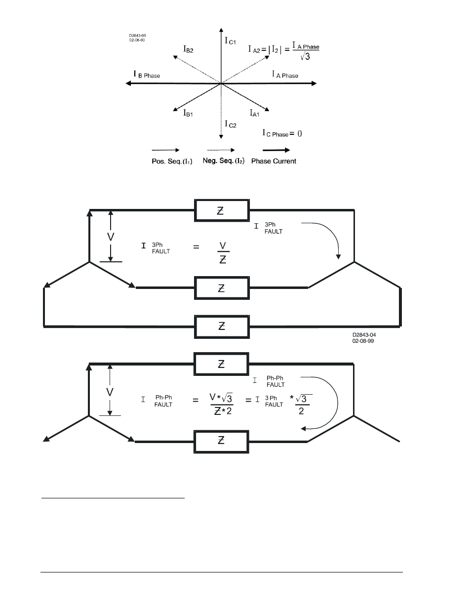
Figure 4-13. Sequence Components for an A-B Fault
Figure 4-14. Phase-to-Phase Fault Magnitude
Negative-Sequence Coordination Settings
The 51Q settings should be checked for coordination with phase-only sensing devices such as
downstream fuses and reclosers and/or ground relays. To plot the negative-sequence time current
characteristics on the same plot for the phase devices, you need to multiply the negative-sequence
element pickup value by the correct multiplier. The multiplier is the ratio of phase current to negative-
sequence current for the fault type for which you are interested. To plot the negative-sequence time
current characteristics on the same plot for the ground devices, you need to multiply the pickup value by
the multiplier for phase-to-ground faults (see Table 4-12).
4-18
BE1-700 Protection and Control
9376700990 Rev M