Voltage protection (be1-700v), Voltage protection (be1-700v) -13 – Basler Electric BE1-700 User Manual
Page 367

Voltage Protection (BE1-700V)
Pull down the Screens menu and select Voltage Protection or click on the Voltage Protection
icon, which is shown at the right margin of this paragraph. This screen has eight folder tabs and
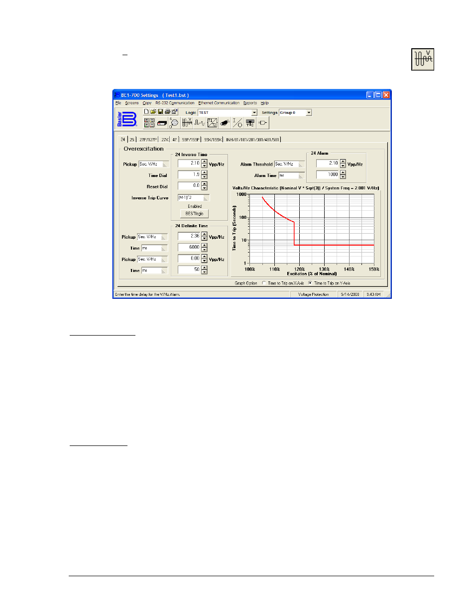
the first tab is 24 (Overexcitation) (see Figure 14-14).
Figure 14-14. Voltage Protection Screen, 24 Tab (Overexcitation)
24 (Overexcitation)
This tab (Figure 14-14) allows you to make the settings for the volts/hertz element. The pull down Pickup
menu allows you to select the relative pickup quantity. The BE1-700 relay measures the voltage input in
secondary voltage. If you want to use primary volts, per unit volts or percent volts, you must coordinate
the settings in CT & VT Setup and Conversions. Whatever the measurement, the method is displayed
besides the settings e.g., V
PP
(voltage, phase-to-phase). Settings for trip Time Dial and Reset Dial can be
adjusted. The Alarm Threshold (percent of pickup) can also be adjusted.
Select the BESTlogic box at the bottom of the 24 Inverse Time column. The status of the logic is shown
above the BESTlogic box. A dialog box (BESTlogic Function Element) opens showing the status of the
element logic and the logic scheme name. If you have a custom logic scheme active, you may change the
status of the element logic by pulling down the menu and selecting from the available choices.
25 (Sync-Check)
This tab (Figure 14-15) allows you to make the settings for the sync-check monitor element. The pull
down Delta Voltage menu allows you to select the relative pickup quantity. The BE1-700 relay measures
the voltage input in secondary voltage. If you want to use primary volts, per unit volts, or percent volts,
you must coordinate the settings in CT & VT Setup and Conversions. Whatever the measurement, the
method is displayed besides the settings, e.g., V
PN
(voltage, phase-to-neutral). Settings for Delta Angle
(Degrees) and Slip Frequency (Hertz) are conventional settings. If you want the 25 phase input frequency
to be greater than the auxiliary input frequency during sync-check, click the Enable box on the screen.
Set the 25VM Live and Dead threshold levels. Set the Dropout Delay (time delay between sensing
dropout and clearing VM1 logic bit) unit of measure and value. Select the 25VM Logic that will set the
VM1 logic bits.
9376700990 Rev M
BE1-700 BESTCOMS Software
14-13