Volts per hertz overexcitation (24) (be1-700v), Volts per hertz overexcitation (24) (be1-700v) -24, Table 13-30. 151n pickup test commands -24 – Basler Electric BE1-700 User Manual
Page 320
Step 6: (Optional.) Repeat Steps 3 through 5 for phase B (Terminals D3 and D4) and phase C
(Terminals D5 and D6). To test independent ground input IG, gain access and transmit SL-
51N=G,0 exit and save. Apply test current to Terminals D7 and D8 while monitoring OUT2 and
repeat Step 4. Verify 51G target on the HMI.
Step 7: (Optional.) Repeat Steps 1 through 4 and Step 6, IG input, for the 151N element. Overwrite the
51 commands entered in Step 2 with the commands of Table 13-30.
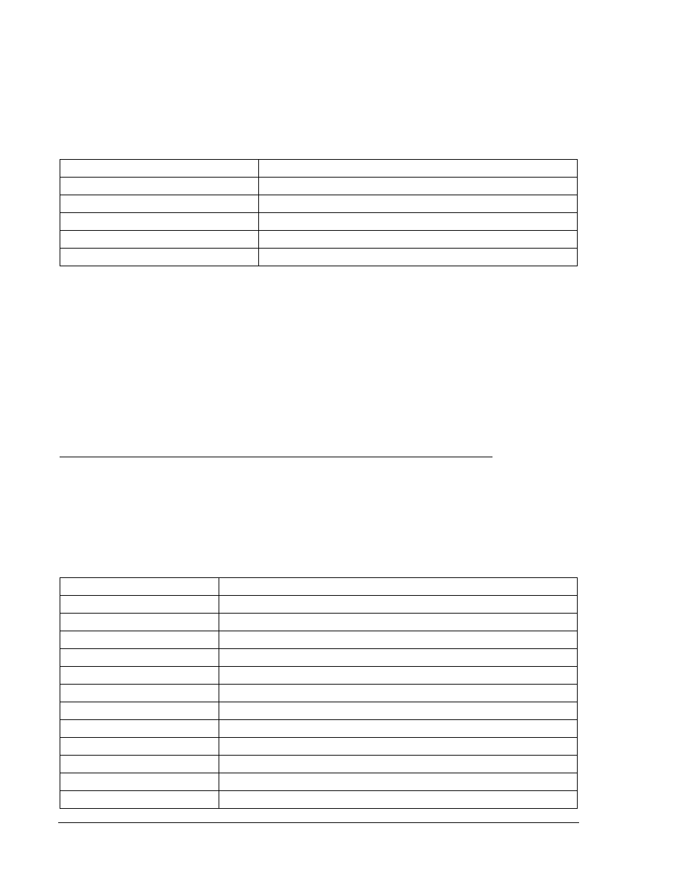
Table 13-30. 151N Pickup Test Commands
Command
Purpose
A=
Gains write access.
SL-151N=G,0
Enables 151N, disables blocking.
SL-VO2=151NT
Enables OUT2 to close for 151N trip.
SG-TRIGGER=151NT,151NPU,0
Enable 151NT or 151NPU to log and trigger fault recording.
EXIT;Y
Exit and save settings.
Step 8: (Optional.) Repeat Steps 1 through 7 for the 51P, 151P, 51N, and 151N elements in Setting
Group 1. Before testing settings in other setting groups, a setting group must be selected using
the CS/CO-GROUP commands. To activate Setting Group 1, CS-GROUP=1 would be entered
to select Setting Group 1 and CO-GROUP=1 would be entered to make Setting Group 1 active.
Also, the pickup settings made in Step 3 (Table 13-27) must be changed to specify the setting
group being tested. To test settings in Group 1, replace the 0 in the S0-x51 commands with a 1
(S1-x51).
Volts per Hertz Overexcitation (24) (BE1-700V)
Purpose: To verify the operating accuracy of the 24 protection element.
Reference Commands: SL-24, SL-VO, SL-GROUP, RG-STAT
Overexcitation, Volts/Hertz Alarm, Integrating Time and Definite Time Pickup Verification
The BE1-700 detects overexcitation conditions with a volts/hertz element that consist of one alarm
setting, one integrating time characteristic with selectable exponents (3 sets of time curves as shown in
Appendix D, Overexcitation (24) Inverse Time Curves), and two definite time characteristics. Note that
V/Hz nominal is 69.3 volts (phase to neutral) x square root 3/60 Hz, or 2.001. That is, at nominal voltage
and frequency (60 Hz system) 1 pu V/Hz = 2.001.
Step 1: Prepare the 24 pickup function for testing by transmitting the commands in Table 13-31 to the
relay. Reset targets.
Table 13-31. V/Hz Alarm, Integrating Time, and Definite Time Test Commands
Command
Purpose
A=
Gains write access.
SL-N=NONE
Zero out custom logic settings. Overwrite with LOGIC=NONE settings.
Y
Confirm overwrite.
SL-N=24
Sets 24 as custom logic name.
SG-VTP=1,4W,PN,PN
Sets VT phase voltage parameters.
SG-NOM=69.3,5.00
Set nominal voltage to 69.3 P to N.
SA-MAJ=31
Enables Major Alarm Light for 24 alarm.
SL-24=1,0
Enables 24, disables blocking.
SL-VO1=24T
Enables OUT1 to close for 24 trip.
SG-TRIG=24T,24PU,0
Enables 24 to log and trigger fault recording.
SG-TARG=24
Enables 24 target.
EXIT;Y
Exit and save settings.
13-24
BE1-700 Testing and Maintenance
9376700990 Rev M