Power up, Communications, Power up -4 – Basler Electric BE1-700 User Manual
Page 300: Communications -4, Table 13-1. input voltages -4
Power Up
Purpose: To verify that the relay performs the power-up sequence.
Step 1: Apply voltage to the input power Terminals A6 and A7. Table 13-1 shows the appropriate input
voltage for each relay style.
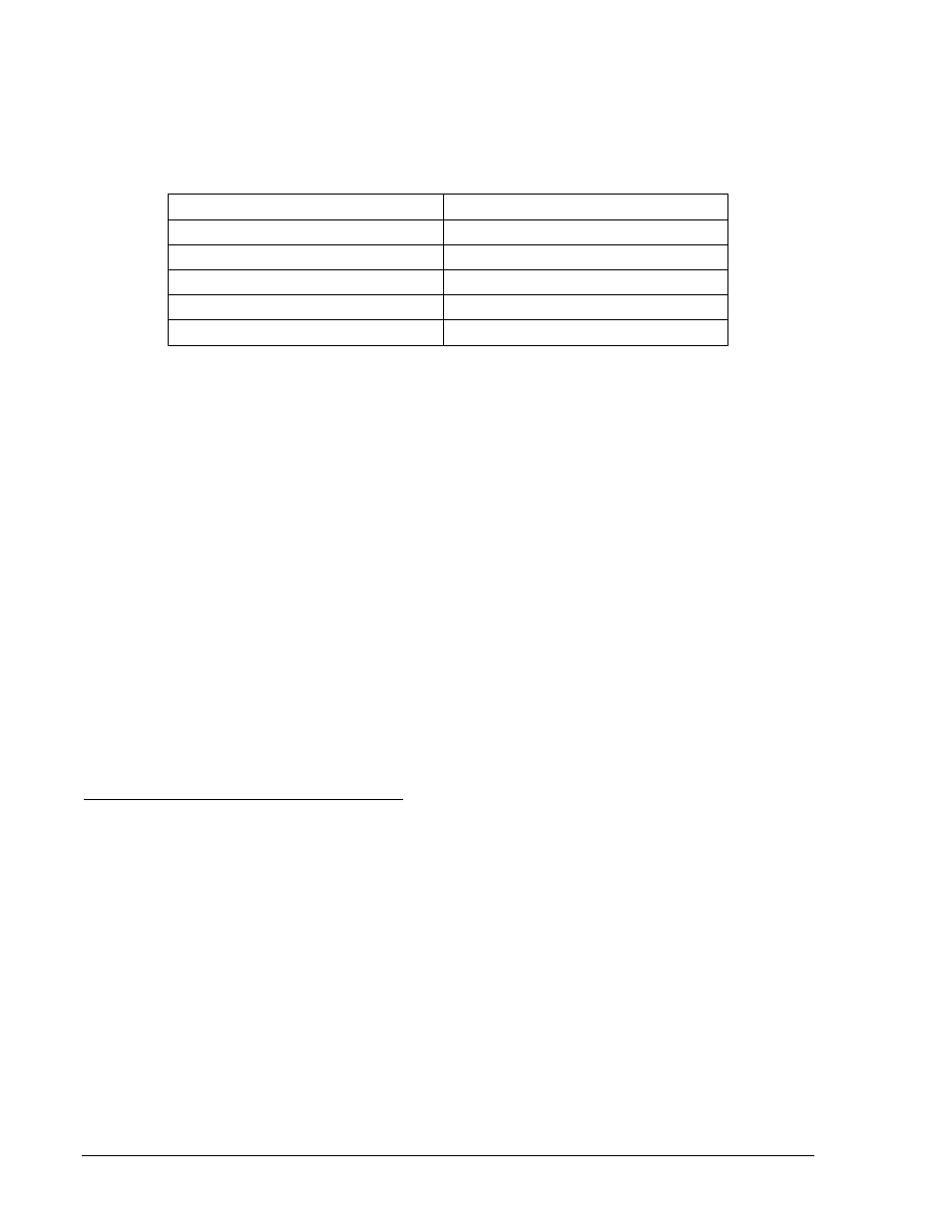
Table 13-1. Input Voltages
Style Number
Voltage Input
BE1-700-xxx1xxN
48 Vdc
BE1-700-xxx2xxN
125 Vac/dc
BE1-700-xxx3xxN
24 Vdc
BE1-700-xxx4xxN
250 Vac/dc
BE1-700-xxx5xxN
125 Vac/dc
∗
∗ Extended holdup option. See Style Chart in Section 1, General Information.
Step 2: Verify that the Power LED is on and that characters are displayed on the HMI display. Upon
power-up, the relay will perform a brief self-test.
During this brief test, all front panel LEDs flash momentarily, the display indicates each step of
the self-test, the relay model, the software version, and then the default display screen. Contact
Basler Electric, Technical Support Services if anything appears out of the ordinary or if an LCD
error message appears.
Communications
Purpose: To verify that the BE1-700 relay communicates through Com ports 0 and 2.
Reference Commands: ACCESS, EXIT
To communicate with the BE1-700 through COM0 or COM2, use a terminal emulation program such as
BESTCOMS - Basler Terminal running on a personal computer (PC) with a serial port that is suitable for
communications. The relay communication default settings are:
• Baud Rate = 9,600 bps
• Data Bits = 8
• Stop Bit =1
• Parity = None
• Flow Control = Xon/Xoff
Set Up the Relay to Communicate with the PC
Step 1: Depress the Up arrow pushbutton on the front panel HMI until the top level of the menu tree is
reached. Depress the Left/Right arrow pushbuttons until Screen 6, General Settings, appears.
Next, depress the Down arrow pushbutton twice to get to Screen 6.1.1, COM0 F-232. This
screen displays the baud rate for the front panel communication port (COM0). Verify that the
baud rate is 9,600 bps (9.6 Kbps).
Step 2: Connect the serial cable between the PC and the front RS-232 port on the relay.
Step 3: Initiate the communication program for your computer.
Step 4: Transmit the command ACCESS= (you may use the shortcut keystrokes and just enter a=).
RESULT: The relay should respond with ACCESS GRANTED: GLOBAL.
Step 5: Transmit EXIT.
Step 6: Connect the male end of the terminal cable to the RS-232 port on a RS-232/485 converter box.
Connect the RS-485 output of the converter box to the relay RS-485 terminals and repeat Steps
1, 2, and 3.
13-4
BE1-700 Testing and Maintenance
9376700990 Rev M