Menu tree, Menu tree -2, Figure 10-2. menu tree branches -2 – Basler Electric BE1-700 User Manual
Page 234
Locator
Description
D, E
Minor Alarm, Major Alarm Indicators – These red LEDs light to indicate that a programmable
alarm has been set. Each indicator can be programmed to annunciate one or more
conditions. Section 6, Reporting and Alarm Functions, provides detailed information about
programming alarms.
F
Trip Indicator – A flashing Trip LED indicates that a protective element is picked up. A
continuously lit LED indicates that a trip output is closed. This red LED is sealed in if a
protective trip has occurred and targets are displayed.
G
Communication Port 0 – This RS-232 serial port can be used to communicate with the relay
using simple ASCII command language. A computer terminal or PC running terminal
emulation software (such as Windows
® HyperTerminal) is required to send commands to
the relay or receive information from the relay.
H
Reset Pushbutton – Pushing this switch will reset the Trip LED, sealed-in Trip Targets, Peak
Demand Currents, and Alarms.
I
Scrolling Pushbuttons – Use these four switches to navigate (UP/DOWN/LEFT/RIGHT)
through the LCD’s menu tree. When in Edit mode, the LEFT and RIGHT scrolling
pushbuttons select the variable to be changed. The UP and DOWN scrolling pushbuttons
change the variable.
J
Edit Pushbutton – Settings changes can be made at the front panel using this switch. When
pushed, this switch lights to indicate that Edit mode is active. When you are finished making
settings changes (using the scrolling pushbuttons) and the Edit switch is pressed again, the
switch light turns off to indicate that your settings changes have been saved. If changes are
not completed and saved within five minutes, the relay will automatically exit the Edit mode
without saving any changes.
K
Identification Label – This label lists the style number, serial number, sensing input current
and voltage range and power supply input voltages.
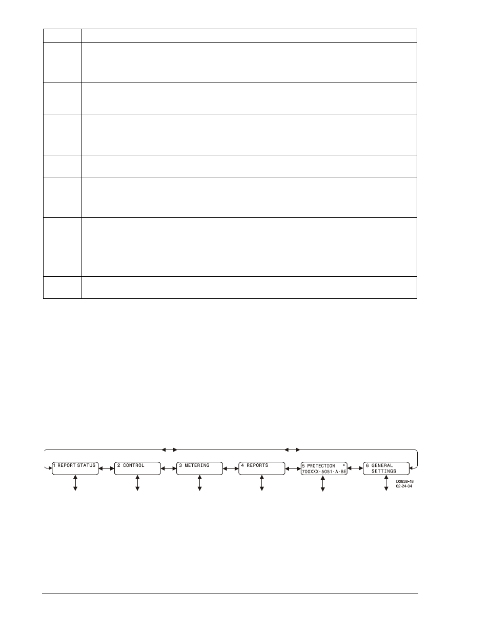
Menu Tree
A menu tree with six branches can be accessed through the front panel controls and display. The LEFT
and RIGHT scrolling pushbuttons are used to view each of the six branches. A greater level of detail in a
menu branch is accessed using the DOWN scrolling pushbutton. Every display screen of the menu tree is
numbered in the upper left hand corner. This number eases navigation below the top level of the menu
tree by indicating the current branch and level in the menu tree structure. Each time a lower menu tree
level is reached, another number is added to the screen number separated by a period. The UP scrolling
pushbutton is used to return to the top of the menu branch.
The six branches of the menu tree are illustrated in Figure 10-2 and summarized in the following
paragraphs.
Figure 10-2. Menu Tree Branches
10-2
BE1-700 Human-Machine Interface
9376700990 Rev M