Table 13-34. v/hz trip time settings -26, Table 13-35. v/hz trip times -26, Table 13-36. v/hz reset time pickup settings -26 – Basler Electric BE1-700 User Manual
Page 322: Ng table 13-34
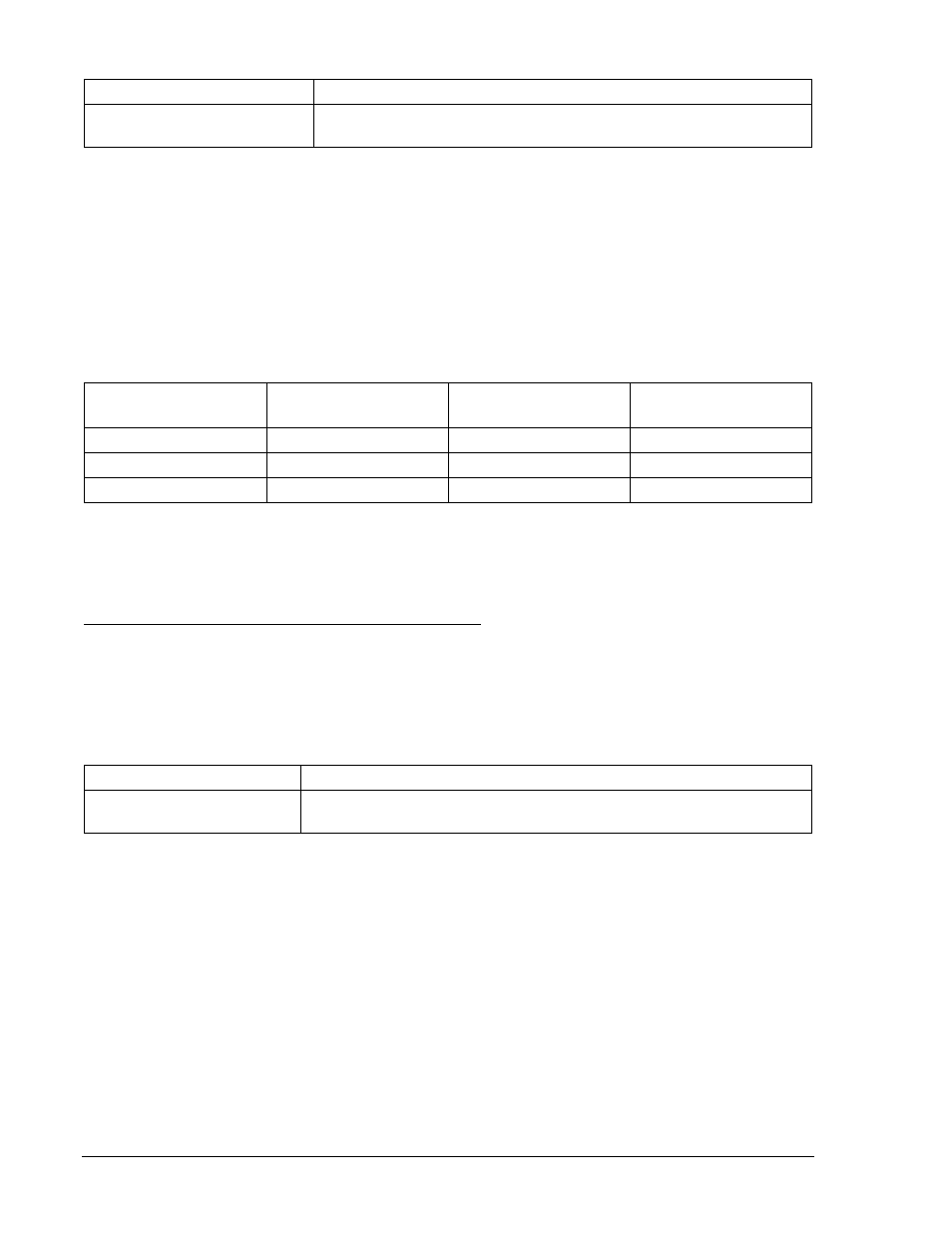
Table 13-34. V/Hz Trip Time Settings
Settings
Purpose
S0-24=2.1,0.5,0.0,2.0
Sets integrating 24 PU at 1.05% of nominal (2.10 V/Hz), Trip Time
Dial = 0.5, Reset Time Dial = 0, Time Curve Exponent = 2.
Step 2: Connect a 120 Vac, three-phase, 50 or 60-hertz voltage source (depending on user's nominal
frequency) to Terminals C13 (A-phase), C14 (B-phase), C15 (C-phase), and C16 (neutral).
Refer to Figure 12-4 for terminal locations.
Step 3: All integrating timing tests are based on % of nominal Volts/Hertz (1 PU value). Refer to
Appendix D of the BE1-700 instruction manual for time curves. Apply A-phase voltage at
nominal frequency and a value of voltage that equals the V/Hz % of nominal shown in Table
13-35 for Time Dial 0.5. Measure the time between the application of voltage and the closure of
OUT1. Verify that the relay operates within
±5% of the values shown in Table 13-35.
Table 13-35. V/Hz Trip Times
Percent of Nominal
V/Hz
Time Dial 0.5
Time Dial 1.0
Time Dial 2.0
110%
50 seconds
100 seconds
200 seconds
120%
12.5 seconds
25 seconds
50 seconds
140%
3.1 seconds
6.3 seconds
12.5 seconds
Step 4: Repeat the test for Time Dial 1.0 and 2.0.
Step 5: (Optional.) Repeat Steps 2 through 4 for the B-phase and C-phase voltage inputs.
Step 6: (Optional.) Repeat Steps 2 through 5 for Setting Group 1.
Overexcitation, Volts/Hertz Linear Reset Time Verification
The following reset time test is an approximation. For a more precise test, use a computer driven test set
and the integration time equations found in Section 4, Protection and Control, Voltage Protection, 24
Element, or Appendix D, Overexcitation (24) Inverse Time Curves.
Step 1: Using Table 13-36 as a guide, transmit the setting commands to the relay.
Table 13-36. V/Hz Reset Time Pickup Settings
Setting
Purpose
S0-24=2.1,0.5,0.2,2.0
Sets 24 PU at 1.05% of nominal (2.10 V/Hz), Trip Time Dial = 0.5,
Reset Time Dial = 0.2, Time Curve Exponent = 2.
Step 2: Connect a 120 Vac, three-phase, 50 or 60-hertz voltage source (depending on user's nominal
frequency) to Terminals C13 (A-phase), C14 (B-phase), C15 (C-phase), and C16 (neutral).
Refer to Figure 12-4 for terminal locations.
Step 3: Apply A-phase voltage at nominal frequency and a value of voltage that equals the V/Hz % of
nominal shown in Table 13-37. Measure the time between the application of voltage and the
closure of OUT1 (12.5 seconds). Remove the test voltage and reapply after 5 seconds has
elapsed.
With a Reset Time Dial setting of 0.2, the total time to reset, after trip is removed, will be
approximately 10 seconds. (See Section 4, Protection and Control, Voltage Protection, for more
details.) Reapplying the test voltage after 5 seconds will yield a trip time of approximately ½ its
original value or 6.25 seconds for Trip Time Dial 0.5 verifying that the reset time delay is
working.
13-26
BE1-700 Testing and Maintenance
9376700990 Rev M