Automatic setting group control, Automatic setting group control -4, Figure 4-3. input control mode 1 -4 – Basler Electric BE1-700 User Manual
Page 60: Table 4-2. setting group binary codes -4
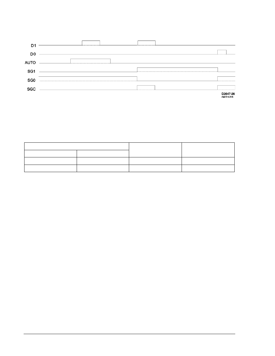
Figure 4-3 shows an example of how the inputs are read when the setting group control function logic is
enabled for Mode 1. Note that a pulse on the D1 input doesn't cause the setting group to change to SG1
because the AUTO input is active.
Figure 4-3. Input Control Mode 1
When the setting group control function block is enabled for Mode 2, inputs D0 and D1 are read as binary
encoded (Table 4-2). A new coded input must be stable for approximately 1 second for the setting group
change to occur. After a setting group change occurs, no setting group change can occur within two times
the SGC alarm on time.
Table 4-2. Setting Group Binary Codes
Binary Code
Decimal Equivalent
Setting Group
D1
D0
0
0
0
SG0
0
1
1
SG1
Automatic Setting Group Control
The relay has built in schemes that may be used to automatically change setting groups. One scheme is
based on the history of the current in the relay. Another scheme is based upon the status of the reclose
function (79) or fuse loss logic (60FL). To enable automatic change of setting groups, setting group
control must be enabled and the <autologic> bit of SL-GROUP command must be a 1 and can be set as
follows:
SL-GROUP = /0,,,,,/0.
When automatic control is enabled, it holds precedence over all manual logic control.
The automatic setting group control may be used to force the relay to change to settings that will
automatically compensate for cold load pickup conditions. For instance, if the relay senses current drop
below a very small amount for a period of time indicating an open breaker, then the relay may move to an
alternate setting group that will allow for the large inrush of current the next time the load is energized.
After current has returned to measurable levels for some period of time, the relay returns to the normal
settings. Another application is to prevent the relay from seeing an overload condition as a fault. If the
relay sees sustained high level phase or unbalance currents that are encroaching on normal trip levels
(indicative of an overload or load imbalance rather than a fault), the relay may move to an alternate
setting group that may accommodate the condition. The relay can be set to alarm for this condition using
the programmable logic alarms.
The relay has the logic to automatically change setting groups based upon the status of the reclose
function (79) or fuse loss (60FL). This scheme allows the relay to have fast and slow curves, for instance,
when the user is applying automatic reclosing into a fault. On the first trip of a fault the relay may use a
setting group with a fast overcurrent curve and/or a low set instantaneous setting, with the intent of
tripping faster than downstream fuses. On subsequent trips, by monitoring the reclose step, the relay
would be in an alternate setting group with a slower overcurrent response and/or a higher or no
instantaneous trip with the intent of operating slower than downstream fuses.
4-4
BE1-700 Protection and Control
9376700990 Rev M