Trip circuit monitor, Trip circuit monitor -14, Table 6-8. breaker alarms settings -14 – Basler Electric BE1-700 User Manual
Page 146
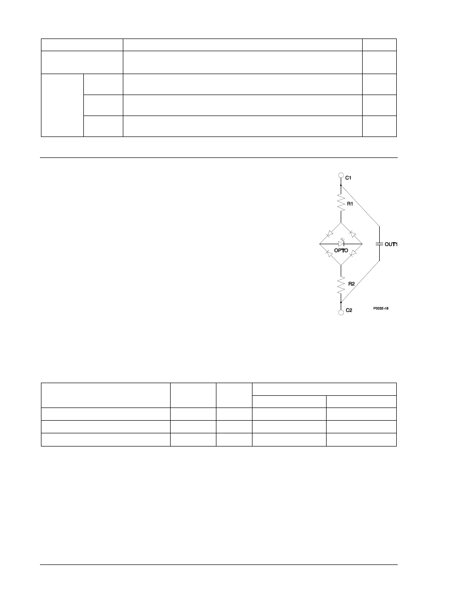
Table 6-8. Breaker Alarms Settings
Setting
Range/Purpose
Default
Mode
0 = Disabled
1 = Duty
2 = Operations
3 = Clearing Time
0
Threshold
Point 1
Mode
0 to 100 in percent, increment = 0.01
0
Point 2
Mode
0 to 99,999 in operations, increment = 1
0
Point 3
Mode
0, 20 to 1,000 in milliseconds (m), seconds (s), or cycles (c). Setting
is reported in milliseconds if less than 1 seconds.
0
TRIP CIRCUIT MONITOR
The trip circuit monitor continually monitors the circuit breaker trip circuit for
voltage and continuity. A closed breaker with no voltage detected across the trip
contacts can indicate that a trip circuit fuse is open or there is a loss of continuity
in the trip coil circuit. Breaker status (open or closed) is obtained through the
breaker status reporting function (configured by the SB-LOGIC command).
The detector circuit used by the trip circuit monitor is hardwired across the
OUT1 contact. This contact is used in all of the preprogrammed logic schemes
as the main trip output. The detector circuit across OUT1 is not polarity sensitive
because the optical isolator used for detecting continuity is connected across a
full wave bridge. See Figure 6-9. The amount of current drawn through the
optical isolator circuit depends on the total input impedance for each power
supply voltage rating (see Table 6-9). Figure 6-10 illustrates typical trip circuit
monitor connections for the BE1-700.
If the breaker status reporting function detects a closed breaker and no trip
circuit voltage is sensed by the trip circuit monitor after 500 milliseconds
(coordination delay time), an alarm bit in the programmable alarms function is
set (OUT1 CKT OPEN) and the OUT1MON BESTlogic variable is set to TRUE.
Table 6-9. Current Draw for each Power Supply Voltage Rating
Power Supply Voltage Rating
R1 = R2 =
R Total
Optical Isolator
Off (25% V)
On (80% V)
24 Vdc
8.2 k
Ω
16.4 k
Ω
6.0 V (0.36 mA)
19.2 V (1.18 mA)
48/125 Vdc
18 k
Ω
36 k
Ω
12.0 V (0.68 mA)
38.4 V (1.02 mA)
125/250 Vdc
47 k
Ω
94 k
Ω
31.25 V (0.71 mA)
100 V (1.06 mA)
Figure 6-9.Trip
Detector Circuit
6-14
BE1-700 Reporting and Alarm Functions
9376700990 Rev M