Operating settings for setting group control, Group control by monitoring fuse loss status -6, Operating settings for setting group control -6 – Basler Electric BE1-700 User Manual
Page 62
GROUP1 = ,,,,791 will cause the relay to change from Setting Group 0 to Setting Group 1 after the first
reclose, but not until the relay senses the breaker has actually closed.
Example:
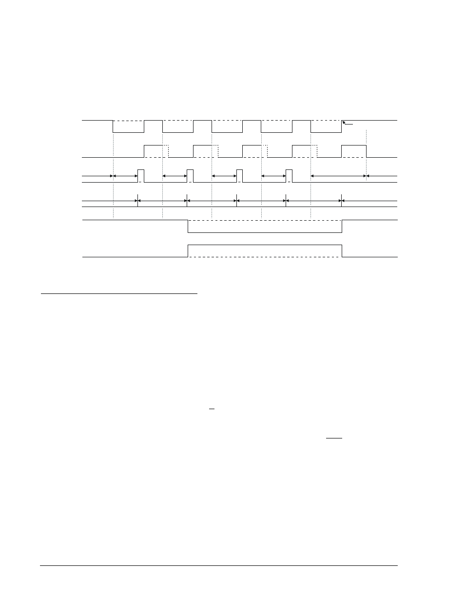
In most common practices, two setting groups are used for emulating a circuit recloser in a fuse saving
scheme (a "fast" curve and a "slow" curve). The settings below call for using Setting Group 0 during
normal operation, Setting Group 1 after reclose 2 and remain in Setting Group 1 until the breaker closed
from lockout. The active group would return to group 0 when the recloser went to reset if any of the close
operations prior to lockout was successful. Refer to Figure 4-4.
Figure 4-4. Example 1 - Change Group on Recloser Shot
Group Control by Monitoring Fuse Loss Status
The active setting group may also be controlled by the status of the fuse loss function (60FL). The relay
may be instructed to change to Setting Group 1 using the command SP-GROUP1=....<60FL>. If the
monitored element in the SP-GROUP command is 60FL, the switch-to threshold, return time, and return
threshold are ignored.
When setting group changes are made via SP-GROUP1=,,,,<60FL>, the relay will stay in the last group
changed until the relay returns to the reset condition. Upon return to the reset condition, the relay restores
Setting Group 0.
Operating Settings for Setting Group Control
Operating settings are made using BESTCOMS. Figure 4-5 illustrates the BESTCOMS screen used to
select operational settings for the Setting Group Selection function. To open the Setting Group Selection
screen, select Setting Group Selection from the Screens pull-down menu. Alternately, settings may be
made using the SP-GROUP ASCII command.
At the top left of the screen is a pull-down menu labeled Logic. This menu allows viewing of the
BESTlogic settings for each preprogrammed logic scheme. A custom logic scheme must be created and
selected in the Logic pull-down menu at the top of the screen before BESTlogic settings can be changed.
See Section 7, BESTlogic Programmable Logic. To the right of the Logic pull-down menu is a pull-down
menu labeled Settings. The Settings menu is used to select the setting group that the elements settings
apply to. Using the pull-down menus and buttons, make the application appropriate settings to the Setting
Group Selection function. Table 4-3 summarizes the operating settings for Setting Group Control.
79RTD
79RTD
79RTD
79RTD
79RTD
RESET
791TD
792TD
793TD
794TD
LOCKOUT
RESET
Manual Close
1
2
3
4
5
1
Closed
BREAKER STATUS
Open
RESET
TIMER
79C
Recloser
STEP
SG0
SG1
P0002-22
09-08-03
4-6
BE1-700 Protection and Control
9376700990 Rev M