Operating settings for sync-check -58, Figure 4-57. voltage protection screen, 25 tab -58 – Basler Electric BE1-700 User Manual
Page 114
BESTlogic Expression Builder, see Section 7, BESTlogic Programmable Logic. Select Done when the
settings have been completely edited.
Table 4-32 summarizes the BESTlogic settings for Sync-Check Protection.
Table 4-32. BESTlogic Settings for Sync-Check Protection
Function
Range/Purpose
Default
Mode
0 = Disabled
1 = Enabled
0
BLK
Logic expression that disables function when TRUE. A
setting of 0 disables blocking.
0
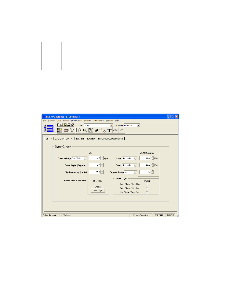
Operating Settings for Sync-Check
Operating settings are made using BESTCOMS. Figure 4-57 illustrates the BESTCOMS screen used to
select operational settings for the Sync-Check element. To open the Voltage Protection screen, select
Voltage Protection from the Screens pull-down menu. Then select the 25 Tab. Alternately, settings may
be made using the S<g>-25 ASCII command or through the HMI using Screens 5.x.2.1 through 5.x.2.4
where g equals the setting group number and x equals 1 (Setting Group 0) and 2 (Setting Group 1).
Figure 4-57. Voltage Protection Screen, 25 Tab
Beside the Logic pull-down menu is a pull-down menu labeled Settings. The Settings menu is used to
select the setting group that the elements settings apply to.
The default unit of measure for Delta Voltage is secondary volts (Sec. Volts). Primary volts (Pri Volts), per
unit volts (Per U Volts), and percent volts (% Volts) can also be selected as the pickup setting unit of
measure.
Table 4-33 summarizes the operating settings for Sync-Check Protection.
4-58
BE1-700 Protection and Control
9376700990 Rev M