Backlight timer, Hmi operations, Entering settings – Basler Electric BE1-700 User Manual
Page 242: Performing control operations, Backlight timer -10, Hmi operations -10, Entering settings -10, Performing control operations -10
To add a screen to the list, select the screen on the HMI simulation by clicking the mouse pointer on the
arrows. Select the Add-> button to add the screen to the list.
Alternately, these settings may be made using the SG-SCREEN ASCII command.
Backlight Timer
A backlight timer turns off the backlight after a period of time set by the SG-BL ASCII command. The
setting range is 0 to 600 seconds. This setting is also programmable on the Clock Display Mode tab
under Reporting and Alarms in BESTCOMS.
HMI OPERATIONS
The following paragraphs describe how the HMI is used to set and control relay functions.
Entering Settings
Settings for protection functions can be edited at menu branch 5, PROTECTION LOGIC of the HMI LCD.
Settings for general and reporting functions can be edited from menu branch 6, GENERAL SETTINGS.
To edit a setting using the manual scrolling pushbuttons, perform the following procedures:
1. Scroll to the screen that displays the function to be edited.
2. Press the Edit pushbutton to gain access. If password security has been initiated for settings, you
will be prompted to enter the appropriate password. See the paragraphs, Entering Passwords, for
details on entering passwords from the HMI. Once access has been gained, the EDIT LED will be
lit and a cursor will appear in the first settings field on the screen.
3. Press the UP or DOWN scrolling key to select the desired setting. Some settings require entering
a number, one character at a time. For example, to enter a 51 pickup as 7.3 amps, you would
press the UP pushbutton until the 7 is showing. Then, press the RIGHT pushbutton to move the
cursor over and press the UP pushbutton until the “.” is showing. Then, press the RIGHT
pushbutton to move the cursor over and press the UP pushbutton until the 3 is showing. Other
settings require scrolling through a list of selections. For example, you would move the cursor
over to the CRV field and then scroll through a list of available TCC curves.
4. Once all of the settings on the screen have been entered, press the Edit pushbutton a second
time and the settings will be validated. If the settings are in range, the screen will flash
CHANGES SAVED and the EDIT LED will go out. If you want to abort the edit session without
changing any settings, press the Reset pushbutton before you press the Edit pushbutton the
second time. The screen will flash CHANGES LOST and the EDIT LED will go out.
Performing Control Operations
Control operations can be executed at Menu Branch 2, CONTROL of the HMI LCD. These functions allow
you to control the state of virtual switches, override logic and control the active setting group, and override
the logic and control the state of output contacts. All of these functions work similarly to the process of
entering settings in that you press the Edit pushbutton, use the UP and DOWN scroll pushbuttons to
select the desired state and press the Edit pushbutton for the action to be executed.
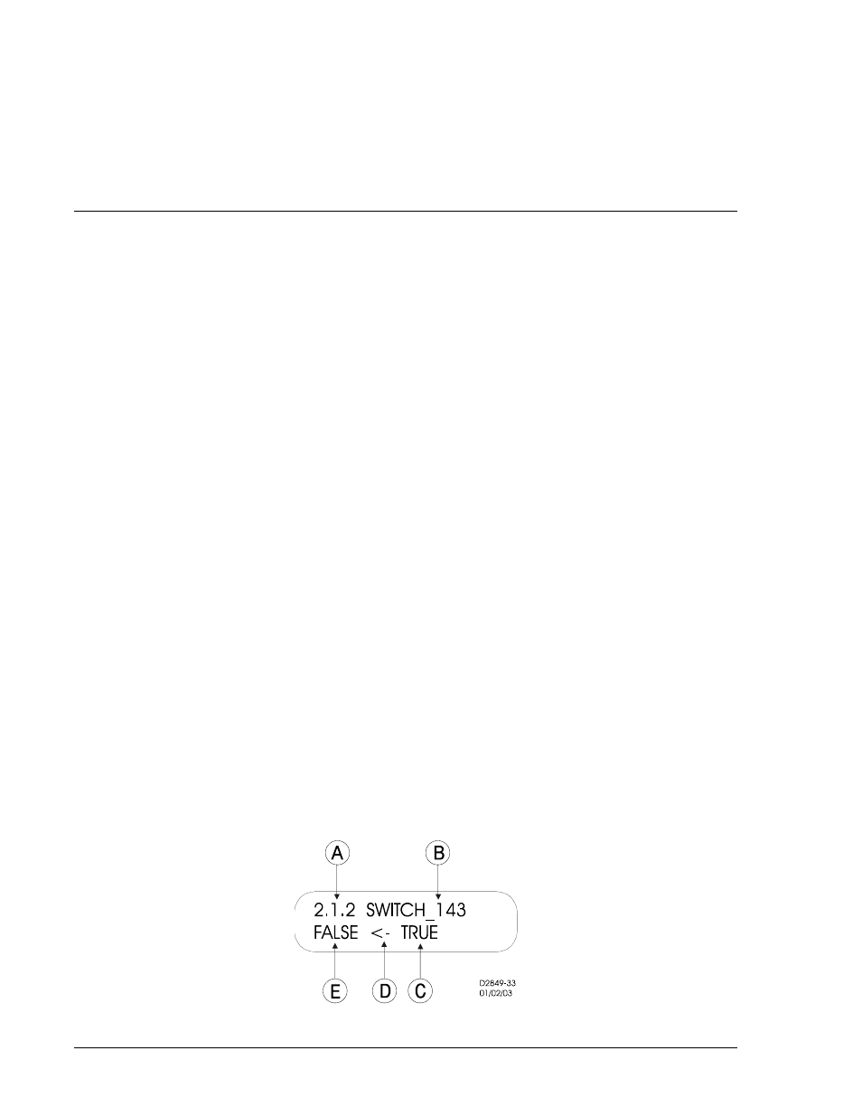
Table 10-3 describes each of the call-outs shown on Figure 10-11. The user-programmable label for this
switch is SWITCH_143. The TRUE (closed) state label has been set to TRUE. In addition, the FALSE
(open) state label has been set to FALSE. The logical mode for this application would be set to Mode 2
(On/Off switch).
Figure 10-11. Virtual Control Switch 143 Screen
10-10
BE1-700 Human-Machine Interface
9376700990 Rev M