Virtual switches, 43 - virtual selector switches, Virtual switches -62 – Basler Electric BE1-700 User Manual
Page 118: 43 - virtual selector switches -62, Table 4-37. 60fl element blocking settings -62
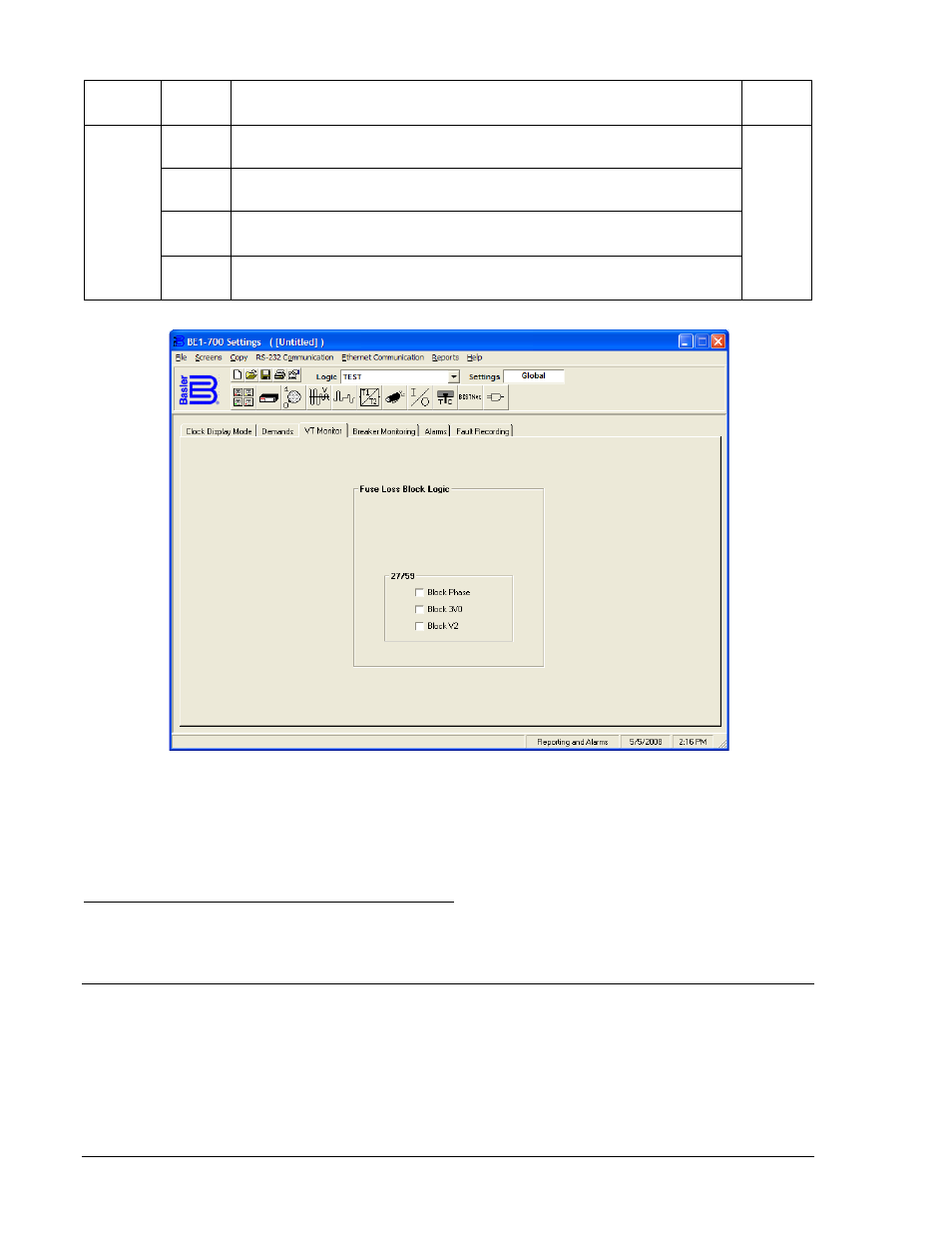
Table 4-37. 60FL Element Blocking Settings
Mode
Input
Setting
Explanation
Default
V Block
DIS
Phase (P), Neutral (N), and Negative-Sequence (Q) voltage functions
are not automatically blocked when 60FL logic is TRUE.
PNQ
P
All functions that use phase voltage are blocked when the 60FL logic is
TRUE. (27P/127P, 59P/159P, and 25)
N
All functions that use 3-phase residual voltage (3V
0
) measurements are
blocked when the 60FL logic is TRUE. (27X, 59X, 159X, - Mode 2)
Q
All functions that use the negative-sequence voltage (V
2
) measurement
are blocked when the 60FL logic is TRUE. (47)
Figure 4-61. Reporting and Alarms Screen, VT Monitor Tab
The 60FL element detects fuse loss and loss of potential by using voltage and current thresholds that are
expressed as a percentage of the nominal voltage and current values. See Section 3, Input and Output
Functions, for information on changing the nominal voltage and current values using the SG-NOM
command.
Retrieving Fuse Loss Detection Status from the Relay
The status of the logic variable can be determined through the ASCII command interface using the RG-
STAT (report general-status) command. See Section 6, Reporting and Alarm Functions, General Status
Reporting, for more information. The status can also be determined using BESTCOMS Metering screen.
VIRTUAL SWITCHES
43 - Virtual Selector Switches
The BE1-700 Digital Protective Relay has two virtual selector switches that can provide manual control,
locally and remotely, without using physical switches and/or interposing relays. Each virtual switch can be
set for one of three modes of operation to emulate virtually any type of binary (two position) switch. An
example would be an application that requires a ground cutoff switch. The traditional approach might be
to install a switch on the panel and wire the output to a contact sensing input on the relay or in series with
4-62
BE1-700 Protection and Control
9376700990 Rev M