Basler Electric BE1-700 User Manual
Page 88
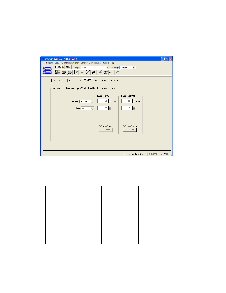
Operating settings are made using BESTCOMS. Figure 4-27 illustrates the BESTCOMS screen used to
select operational settings for the auxiliary Under/Overvoltage element. To open the Voltage Protection
screen for Under/Overvoltage elements, select Voltage Protection from the Screens pull-down menu.
Then select either the 27X or the 59X/159X tab. Alternately, settings may be made using the S<g>-59X,
S<g>-159X, and S<g>-27X ASCII commands or through HMI Screens 5.x.3.2 (27x), 5.x.8.2 (59x), and
5.x.8.4 where x equals 1 (Setting Group 0) or 2 (Setting Group 1).
Beside the Logic pull-down menu is a pull-down menu labeled Settings. The settings menu is used to
select the setting group that the elements settings apply to.
Figure 4-27. Voltage Protection Screen, 59X/159X Tab
Table 4-20 summarizes the operating settings for Auxiliary Undervoltage/Overvoltage Protection.
Table 4-20. Operating Settings for Auxiliary Undervoltage/Overvoltage Protection
Setting
Range
Increment
Unit of Measure
Default
Pickup
0 = Disabled
1 to 150
0.1 for 0 to 99.9
1.0 for 100 to 150
Secondary Volts
0
Inhibit
27X only
0 = Disabled
1 to 150
0.1
Secondary Volts
0
Time Delay
50 to 999 milliseconds
1
Milliseconds
50 ms
1 to 600 seconds
0.1 for 1.0 to 9.9
Seconds
1.0 for 10 to 600
Seconds
3 to 36,000 cycles (60 Hz)
∗
Cycles
2.5 to 30,000 cycles (50 Hz)
∗ Time delays less than 10 cycles can be entered to the nearest 0.1 cycles from the front panel HMI. All
time delays can be entered to the nearest 0.01 cycles from the ASCII command interface. Time delays
entered in cycles are converted to milliseconds or seconds. Increment precision after conversion is limited
to that appropriate for each of those units of measure.
4-32
BE1-700 Protection and Control
9376700990 Rev M