Reclose wait (wait) -49, Drive to lockout/block recloser (dtl/blk) -49, Pilot initiate (pi) and pilot reclose (79p) -49 – Basler Electric BE1-700 User Manual
Page 105: Close (79c) -49, Recloser running (79rng) -49, Lockout (79lo) -49, Reset timer (79rst) -49, Sequence controlled block (79scb) -49, Figure 4-48. 79scb logic -49
Reclose Wait (WAIT)
A TRUE signal at this input disables the reclosing function. In this condition, recloser timing is interrupted.
When this input returns to a FALSE state, reclosing is enabled and recloser timing resumes.
Drive to Lockout/Block Recloser (DTL/BLK)
When TRUE, this input forces the reclosing function into the Lockout position. Lockout persists for the
period defined by the Reset time after the DTL/BLK input becomes FALSE and the breaker is closed.
Pilot Initiate (PI) and Pilot Reclose (79P)
If the recloser is in the reset state upon receiving a pilot initiate (PI) input signal, the reclose logic issues a
pilot reclose output (79P) after the programmed time delay. The initiate logic shall be held for 100 ms in
order to assure that it will be there when the STATUS input and the PI input are compared. If the recloser
is in the reset state and the PI and RI inputs are received simultaneously with the breaker status open,
the 79P timer shall be initiated instead of the 791 timer. After the 79P shot, only the RI input is monitored
to start the delayed reclosing sequence if the 52 status input indicates that the breaker opened before the
reset time has expired.
If the recloser is in reset, and if the time delay for the pilot reclose (79P) is non-zero, and if the 1
st
reclose
time delay is zero, upon a trip, a reclose initiate (RI) will cause the relay to use the 2
nd
reclose time delay
instead of the 1
st
reclose time delay.
Close (79C)
The 79C output becomes TRUE at the end of each reclose time delay and remains TRUE until the
breaker closes. Any of the following conditions will cause the 79C output to become FALSE:
• The STAT input indicates that the breaker is closed.
• The reclose fail timer times out.
• The recloser goes to Lockout.
• The WAIT logic is asserted.
Recloser Running (79RNG)
The 79RNG output is TRUE when the reclose is running (i.e., not in Reset or Lockout). This output is
available to block the operation of a load tap changer on a substation transformer or voltage regulator
during the fault clearing and restoration process.
Lockout (79LO)
This output is TRUE when the recloser is in the Lockout state. It remains TRUE until the recloser goes to
the Reset state. The recloser will go to Lockout if any of the following conditions exist:
• More than the maximum number of programmed recloses is initiated before the recloser returns
to the Reset state.
• The DTL/BLK input is TRUE.
• The Reclose Fail (79F) is TRUE.
• The maximum reclose cycle time is exceeded.
Reset Timer (79RST)
The 79RST output provides reset indication and is TRUE when the recloser is in the reset position.
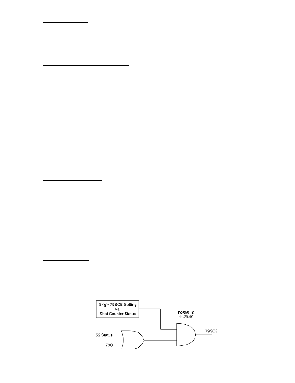
Sequence Controlled Block (79SCB)
This output becomes TRUE when either the 52 status input OR the 79C input is TRUE AND the
sequence operation (shot counter) matches one of the programmed steps of the S<g>-79SCB command.
Figure 4-48 illustrates 79SCB logic.
Figure 4-48. 79SCB Logic
9376700990 Rev M
BE1-700 Protection and Control
4-49