Relay connections, Relay connections -3, Figure 12-2. relay cutout dimensions -3 – Basler Electric BE1-700 User Manual
Page 273
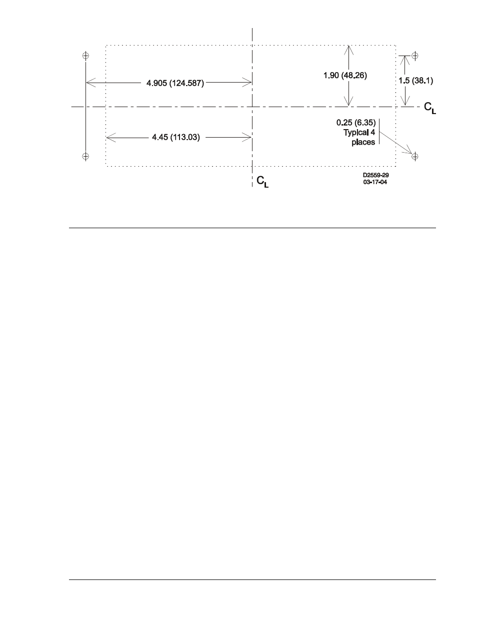
Figure 12-2. Relay Cutout Dimensions
RELAY CONNECTIONS
Connections to the relay are dependent on the application and logic scheme selected by the user. As a
result, not all of the relay’s inputs and outputs may be used for a given application. Before energizing a
relay, make sure the connections match the options associated with the model and style number found on
the relay nameplate. Refer to the style number identification charts in Figure 1-1 for available options. Be
sure to use the correct input power for the specified power supply. Incorrect wiring may result in damage
to the relay.
Figure 12-3 shows the rear panel connections for the current relay case and Figure 12-4 shows the rear
panel connections for the voltage relay case.
9376700990 Rev M
BE1-700 Installation
12-3