Bestlogic, Function block logic settings, Bestlogic -2 – Basler Electric BE1-700 User Manual
Page 30: Function block logic settings -2
BESTLOGIC
Each of the protection and control functions in the BE1-700 is implemented as an independent function
block that is equivalent to a single function, discrete device counterpart. Each independent function block
has all of the inputs and outputs that the discrete component counterpart might have. Programming
BESTlogic is equivalent to choosing the devices required by your protection and control scheme and
drawing schematic diagrams to connect the inputs and outputs to obtain the desired operational logic.
The concept is the same but the method is different in that you choose each function block by enabling it
and use Boolean logic expressions to connect the inputs and outputs. The result is that in designing your
system, you have even greater flexibility than you had using discrete devices. An added benefit is that
you are not constrained by the flexibility limitations inherent in many multifunction relays.
One user programmable, custom logic scheme created by the user may be programmed and saved in
memory. To save you time, several preprogrammed logic schemes have also been provided. Any of the
preprogrammed schemes can be copied into the programmable logic settings without the user having to
make any BESTlogic programming.
There are two types of BESTlogic settings: function block logic settings and output logic settings. These
are described briefly in the following paragraphs. Detailed information on using BESTlogic to design
complete protection and control schemes for the protected circuit can be found in Section 7, BESTlogic
Programmable Logic, and Section 8, Application.
Characteristics of Protection and Control Function Blocks
As stated before, each function block is equivalent to a discrete device counterpart. For example, the
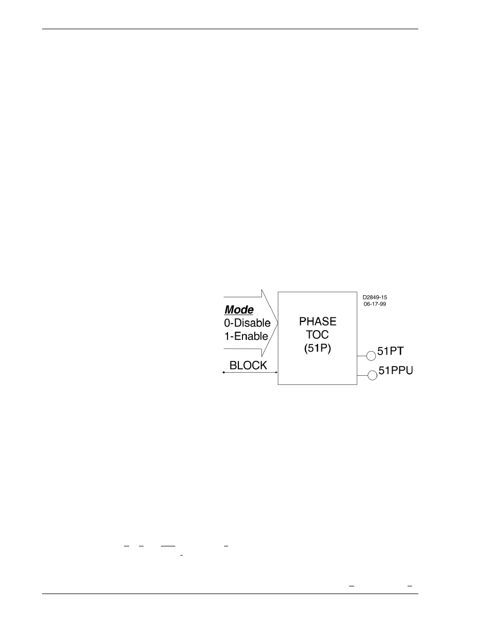
phase time-overcurrent function block in the BE1-700 relay has all of the characteristics of Basler BE1
relays with similar functionality. Figure 2-1 is a logic drawing showing the inputs and outputs.
One input:
• BLK (block 51P operation)
Two mode settings:
• Enable 51P operation
• Disable 51P operation
Two outputs:
• 51PT (51 Phase Trip)
• 51PPU (51 Phase Pickup)
Four operational settings:
• Pickup
• Time Delay
• Characteristic Curve
Figure 2-1. 51 Time Overcurrent Logic (BE1-700C)
Of the above characteristics, the four operational settings are not included in the logic settings. They are
contained in the protection settings. This is an important distinction. Since changing logic settings is
similar to rewiring a panel, the logic settings are separate and distinct from the operational settings such
as pickups and time delays.
Function Block Logic Settings
To use a protection or control function block, there are two items that need to be set: Mode and Input
Logic. The mode is equivalent to deciding which devices you want to install in your protection and control
scheme. You then must set the logic variables that will be connected to the inputs.
For example, the 51N function block has three modes (disabled, three-phase summation (3Io), and
ground), and one input, block (torque control). To use this function block, the logic setting command might
be SL-51N=1,/IN2 for Set Logic-51N to be Mode 1 (three-phase and neutral) with the function blocked
when Contact Sensing Input 2 is not (/) energized. Contact Sensing Input 2 would be wired to a ground
relay enable switch.
As noted before, the protection settings for this function block, pickup, time dial, and curve must be set
separately in the setting group settings. The setting might be S0-51N=6.5,2.1,S1R for Setting in group 0 -
2-2
BE1-700 Quick Start
9376700990 Rev M