Bestlogic settings for sync-check protection -57 – Basler Electric BE1-700 User Manual
Page 113
Also note that VM performs three of three testing for all connections. For 3W and 4W, phases A, B, and C
are actually tested. For single-phase connections, the terminals are connected in parallel as described
above and the single-phase is tested three times.
Measuring slip frequency directly allows the function to rapidly determine if systems are in synchronism
and requires no timer or inherent delay (as compared to systems that check only that phase angle is held
within a window for some stretch of time). The moment parameters a), b), and c) in the previous
paragraph are met, the systems may be considered in synchronism and the output becomes TRUE. Refer
to Section 5, Metering, for more information about slip frequency measurement.
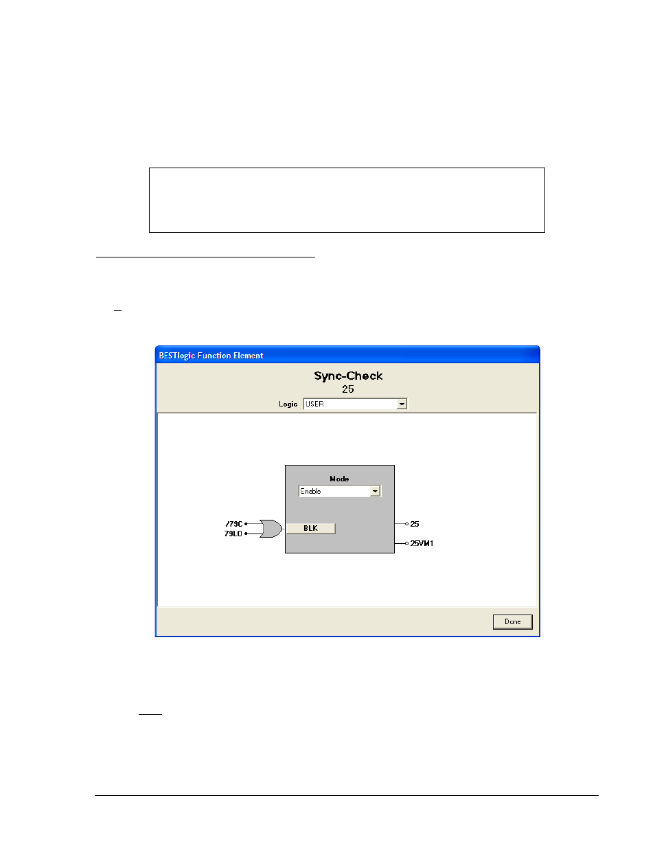
BESTlogic Settings for Sync-Check Protection
BESTlogic settings are made from the BESTlogic Function Element screen in BESTCOMS. Figure 4-56
illustrates the BESTCOMS screen used to select BESTlogic settings for the Sync-Check element. To
open the BESTlogic Function Element screen for the Sync-Check element, select Voltage Protection from
the Screens pull-down menu. After selecting the 25 Tab, select the BESTlogic button. Alternately, settings
may be made using SL-25 ASCII command.
Figure 4-56. BESTlogic Function Element Screen, 25
At the top center of the BESTlogic Function Element screen is a pull-down menu labeled Logic. This
menu allows viewing of the BESTlogic settings for each preprogrammed logic scheme. A custom logic
scheme must be created and selected in the Logic pull-down menu at the top of the screen before
BESTlogic settings can be changed. See Section 7, BESTlogic Programmable Logic.
Enable the Sync-Check function by selecting its mode of operation from the Mode pull-down menu. To
connect the element's inputs, select the button for the corresponding input in the BESTlogic Function
Element screen. The BESTlogic Expression Builder screen will open. Select the expression type to be
used. Then, select the BESTlogic variable, or series of variables to be connected to the input. Select
Save when finished to return to the BESTlogic Function Element screen. For more details on the
NOTE
If the 60FL element logic is TRUE and V block is enabled for phase blocking (P),
the 25 element will be blocked. For more information on the 60FL function, see
Voltage Transformer Fuse Loss Detection later in Section 4.
9376700990 Rev M
BE1-700 Protection and Control
4-57