Table 13-18. 50tq/150tq time delay settings -19, Table 13-19. 50tn/150tn pickup test commands -19 – Basler Electric BE1-700 User Manual
Page 315
Command
Purpose
SG-CT=1
Sets CT ratio at 1.
SG-TRIGGER=50TQT+50TQPU,
150TQT+150TQPU,0
Enable 50TQT and 150TQT to log and trigger fault recording.
EXIT;Y
Exit and save settings.
Step 3: Using Table 13-18, transmit the first column of setting commands for your sensing input type
(substitute 0.1 for 1 amp CT).
Table 13-18. 50TQ/150TQ Time Delay Settings
Pickup and Time Delay Settings
Purpose
2 Second TD
5 Second TD
10 Second TD
S0-50TQ=0.5,2S
S0-50TQ=0.5,5S
S0-50TQ=0.5,10S
Sets 50TQ TD.
For a single-phase input test, I
2
= Ia ÷ 3. Therefore, the relay should pick up at a value of three times the
setting value when applying only a single-phase input. For example, to determine the pickup current value
required for a 1-amp relay with a pickup setting of 0.1, it would require 0.1 times 3 or 0.3 amperes of input
current.
Step 4: Step the applied A-phase current to 110% of pickup. Measure the time delay and verify the
accuracy of the 50TQ time delay setting, OUT1, and 150TQ, OUT2. Timing accuracy is
±5
percent or
±3 cycles of the time delay setting.
Step 5: Repeat Step 2 and 3 for the middle and higher time delay settings in Table 13-18.
Step 6: (Optional.) Repeat Steps 3 through 5 for phase B (Terminals D3 and D4) and phase C
(Terminals D5 and D6).
Step 7: (Optional.) Repeat Steps 1 through 6 for Setting Group 1.
50TN/150TN (Independent Ground Input IG) Pickup and Dropout Verification
Purpose: To verify the operation of the 50TN and 150TN elements for IG input.
Reference Commands: SL-50TN/150TN
Step 1: Connect a current source to Terminals D7 and D8 (IG).
Step 2: Prepare the 50TN and 150TN elements for testing by transmitting the commands in Table 13-19
to the relay. Reset targets.
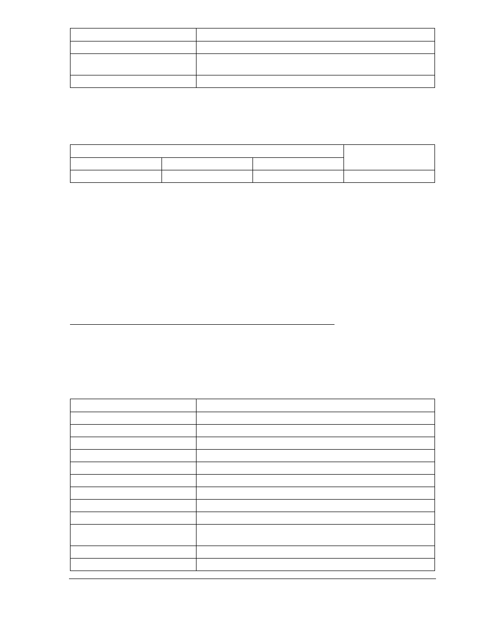
Table 13-19. 50TN/150TN Pickup Test Commands
Command
Purpose
A=
Gains write access.
SL-N=NONE
Zero out custom settings. Overwrite with LOGIC=NONE settings.
Y
Confirm overwrite.
SL-N=50/150TN
Sets 50/150TN as custom logic name.
SL-50TN=G,0
Enables 50TN, disables blocking.
SL-150TN=G,0
Enables 150TN, disables blocking.
SL-VO1=50TNT
Enables OUT1 to close for 50TN trip.
SL-VO2=150TNT
Enables OUT2 to close for 150TN trip.
SG-CT=1
Sets CT ratio at 1.
SG-TRIGGER=50TNT+50TNPU,
150TNT+150TNPU,0
Enable 50TNT and 150TNT to log and trigger fault recording.
SG-TARG=50TN/150TN
Enables 50TN and 150TN targets.
EXIT;Y
Exit and save settings.
9376700990 Rev M
BE1-700 Testing and Maintenance
13-19