Basler Electric BE1-700 User Manual
Page 93
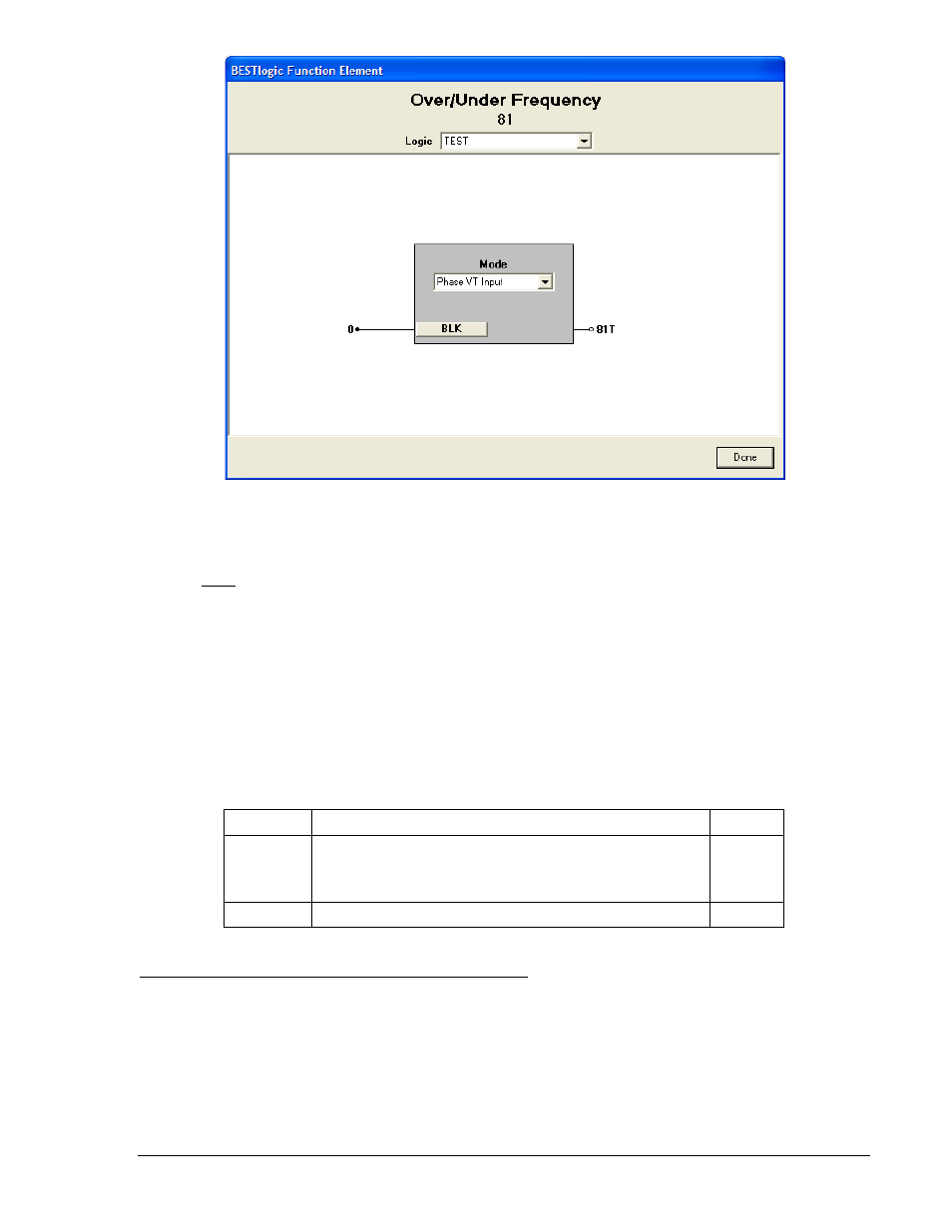
Figure 4-32. BESTlogic Function Element Screen, 81
At the top center of the BESTlogic Function Element screen is a pull-down menu labeled Logic. This
menu allows viewing of the BESTlogic settings for each preprogrammed logic scheme. A custom logic
scheme must be created and selected in the Logic pull-down menu at the top of the screen before
BESTlogic settings can be changed. See Section 7, BESTlogic Programmable Logic. Enable the
Over/Under Frequency function by selecting its mode of operation from the Mode pull-down menu. To
connect the elements inputs, select the button for the corresponding input in the BESTlogic Function
Element screen. The BESTlogic Expression Builder screen will open. Select the expression type to be
used. Then, select the BESTlogic variable, or series of variables to be connected to the input. Select
Save when finished to return to the BESTlogic Function Element screen. For more details on the
BESTlogic Expression Builder, see Section 7, BESTlogic Programmable Logic. Select Done when the
settings have been completely edited.
BESTlogic settings for Over/Under Frequency Protection are summarized in Table 4-23.
Table 4-23. BESTlogic Settings for Over/Under Frequency Protection
Function
Range/Purpose
Default
Mode
0 = Disabled
1 = Enabled on VP Input
X = Enabled on VX Input
1
BLK
Logic expression that disables function when TRUE.
0
Operating Settings for Over/Under Frequency Protection
Operating settings for the 81 elements consist of pickup values, time delay values, and a mode setting
that defines whether an element provides under or over frequency protection and is selectable from a
pull-down menu under each element tab. The pickup value determines the value of frequency required for
the element to start timing toward a trip. The time delay value determines the length of time between
reaching the pickup value and tripping. Time delays can be set in milliseconds, seconds, or cycles. The
default is milliseconds if no unit of measure is specified. Minimum timing resolution is two cycles. A time
delay setting of zero makes the element instantaneous with no intentional time delay.
Operating settings are made using BESTCOMS. Table 4-33 illustrates the BESTCOMS screen used to
select operational settings for the Over/Under Frequency element. To open the BESTlogic Function
9376700990 Rev M
BE1-700 Protection and Control
4-37