Table 6-18. programmable alarm settings -30 – Basler Electric BE1-700 User Manual
Page 162
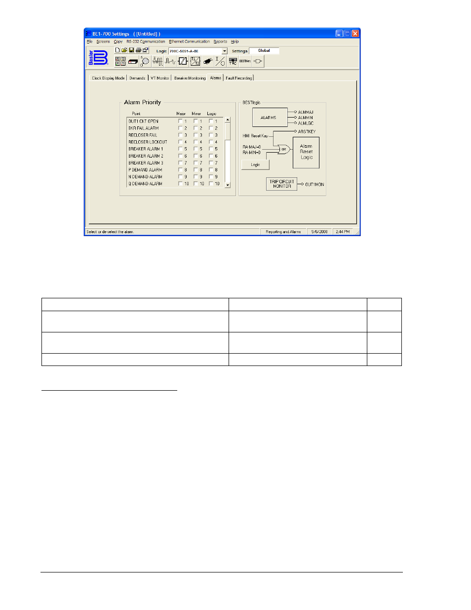
Figure 6-21. Reporting and Alarms Screen, Alarms Tab
Table 6-18 summarizes major, minor, and logic programmable alarm settings.
Table 6-18. Programmable Alarm Settings
Setting
Range/Purpose
Default
Major alarm points (drives Major Alarm LED and
ALMMAJ logic variable).
List of alarm functions per Table 6-17.
0
Minor alarm points (drives Minor Alarm LED and
ALMMAJ logic variable).
List of alarm functions per Table 6-17.
29
Logic alarm points (drives ALMLGC logic variable).
List of alarm functions per Table 6-17.
0
Retrieving and Resetting Alarm Reports
When an alarm condition occurs, the appropriate front panel LED lights and HMI Screen 1.3 is displayed.
(See Section 10, Human-Machine Interface, for more information about automatic display priority logic.)
The HMI display scrolls between displaying all active alarm points. This includes alarms that are not
programmable (relay trouble alarms). Any latched alarms that are not currently active can be reset by
pressing the HMI Reset key. See Figure 6-22 for logic.
Logic variables for ALMMAJ, ALMMIN, and ALMLGC can also be set to operate any of the output
contacts to give an indication that an alarm condition exists. Section 7, BESTlogic Programmable Logic,
provides more details about this feature.
The status of the three front-panel LEDs (Relay Trouble, Minor Alarm, and Major Alarm) can be read
through the communication ports by using the RG-STAT command. Alarm status is given in the
DIAG/ALARM line of the General Status Report. Refer to the General Status Reporting subsection for
more information about obtaining relay status with the RG-STAT command. Figure 6-22 shows the alarm
reset logic.
6-30
BE1-700 Reporting and Alarm Functions
9376700990 Rev M