Figure 12-17. rs-232 pin-outs -19, Figure 12-18. personal computer to be1-700 -19, Figure 12-19. modem to be1-700 -19 – Basler Electric BE1-700 User Manual
Page 289
Advertising
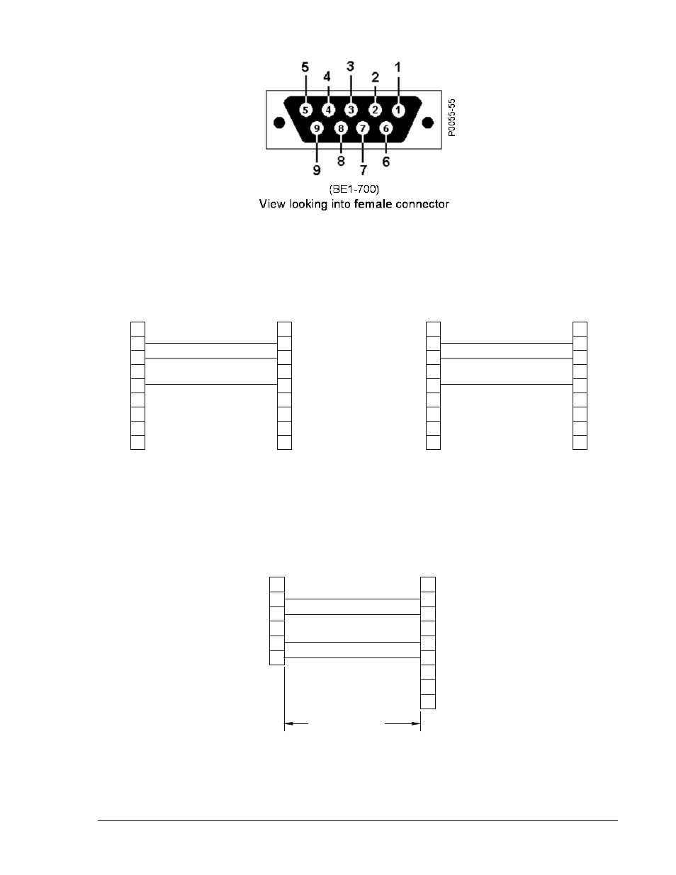
Figure 12-17. RS-232 Pin-outs
Figure 12-18. Personal Computer to BE1-700
Figure 12-19. Modem to BE1-700
5
4
3
2
1
1
2
3
4
5
RXD
TXD
SGND
TXD
RXD
N.C.
SGND
FEMALE DB-9, DCE
MALE DB-9, DTE
9
6
7
8
N.C.
N.C.
TO BE1-700
9-PIN PC-AT
N.C.
N.C.
N.C.
D2848-46
02/11/04
25-PIN PC-XT
TO BE1-700
N.C.
8
7
6
9
MALE DB-25, DTE
FEMALE DB-9, DCE
SGND
N.C.
RXD
TXD
5
4
3
2
1
3
2
7
N.C.
N.C.
N.C.
N.C.
N.C.
RXD
TXD
20
7
6
3
2
1
1
2
3
4
5
TXD
RXD
+5V
SGND
TX D
RXD
N.C.
SGN D
50 FEET
MAX.
FEMALE DB-9, DCE
FEMALE DB-25, DCE
D2881-39
02/11/04
DT R
9
6
7
8
N.C.
N.C.
N.C.
N.C.
GND
TO BE1-700
TO 25 PIN MODEM
+10V
9376700990 Rev M
BE1-700 Installation
12-19
Advertising
This manual is related to the following products: