101 - virtual breaker control switch, 101 - virtual breaker control switch -65 – Basler Electric BE1-700 User Manual
Page 121
CS/CO-x43 Command Examples:
Example 1.
Read the current status of Virtual Switch 43.
>CO-43
0
Example 2.
Momentarily toggle the state of Switch 43 to closed.
>CS-43=P
43=P SELECTED
>CO-43=P
43=P EXECUTED
Example 3.
An example of an operate command not matching the select command.
>CO-143=1
ERROR:NO SELECT
Retrieving Virtual Selector Switch Status from the Relay
The state of each virtual selector switch can be determined from HMI Screen 1.5.4. This information is
also available through the ASCII command interface by using the RG-STAT command and on
BESTCOMS Metering screen. See Section 6, Reporting and Alarm Functions, General Status Reporting,
for more information.
HMI Screens 2.1.1 and 2.1.2 provide switch control and can also display the current status of their
respective switches. ASCII command CO-x43 returns the state of each virtual selector switch in a read-
only mode. See the previous Example 1.
101 - Virtual Breaker Control Switch
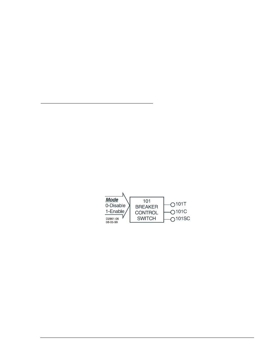
The virtual breaker control switch (shown in Figure 4-64) provides manual control of a circuit breaker or
switch without using physical switches and/or interposing relays. Both local and remote control is
possible. A virtual switch can be used instead of a physical switch to reduce costs with the added benefit
that the virtual switch can be operated both locally from the HMI and remotely from a substation computer
or modem connection to an operator's console.
Figure 4-64. Virtual Breaker Control Switch Logic Block
The breaker control switch emulates a typical breaker control switch with a momentary close, spring
return, trip contact (output 101T), a momentary close, spring return, close contact (output 101C), and a
slip contact (output 101SC). The slip contact output retains the status of the last control action. That is, it
is FALSE (open) in the after-trip state and TRUE (closed) in the after-close state. Figure 4-65 shows the
state of the 101SC logic output with respect to the state of the 101T and 101C outputs.
When the virtual control switch is controlled to trip, the 101T output pulses TRUE (closed) for
approximately 200 milliseconds and the 101SC output goes FALSE (open). When the virtual control
switch is controlled to close, the 101SC output pulses TRUE (closed). The status of the slip contact output
is saved to nonvolatile memory so that the relay will power up with the contact in the same state as when
the relay was powered down.
9376700990 Rev M
BE1-700 Protection and Control
4-65