Basler Electric BE1-700 User Manual
Page 59
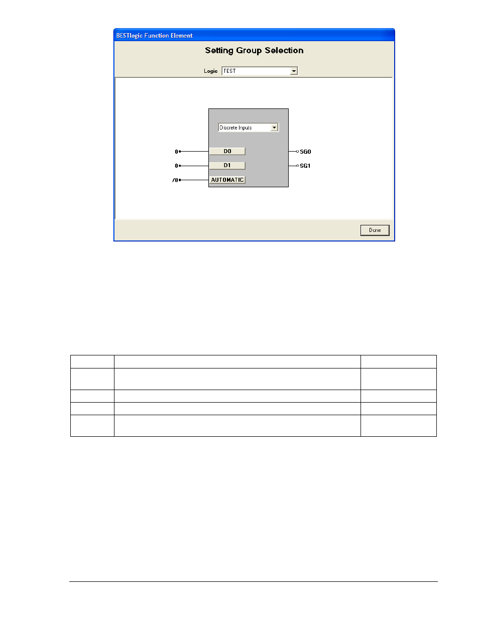
Figure 4-2. BESTlogic Function Element Screen, Setting Group Selection
Enable the Setting Group Selection function by selecting its mode of operation from the Mode pull-down
menu. To connect the functions inputs, select the button for the corresponding input in the BESTlogic
Function Element screen. The BESTlogic Expression Builder screen will open. Select the expression type
to be used. Then, select the BESTlogic variable, or series of variables to be connected to the input.
Select Save when finished to return to the BESTlogic Function Element screen. For more details on the
BESTlogic Expression Builder, see Section 7, BESTlogic Programmable Logic. Select Done when the
settings have been completely edited. Table 4-1 summarizes the BESTlogic settings for Setting Group
Control.
Table 4-1. BESTlogic Settings for Setting Group Control
Function
Range/Purpose
Default
Mode
0 = Disabled, 1 = Discrete Inputs, 2 = Binary Inputs (If Auto mode is
desired, logic mode must be either 1 or 2.)
1 (Discrete Inputs)
D0
Logic expression. Meaning is dependent upon the Mode setting.
0
D1
Logic expression. Meaning is dependent upon the Mode setting.
0
Automatic
Logic Expression. When TRUE, automatic control is enabled and
when FALSE, logic control is enabled.
/0
Manual (logic) control reads the status of the logic inputs to the setting group control function block to
determine what setting group should be active. For the logic inputs to determine which setting group
should be active, the AUTO input must be logic 0. The function block logic mode setting determines
how it reads these logic inputs. There are three possible logic modes as shown in Table 4-1.
When the setting group control function block is enabled for Mode 1, there is a direct correspondence
between each discrete logic input and the setting group that will be selected. That is, asserting input D0
selects SG0 and asserting input D1 selects SG1. The active setting group latches in after the input is read
so they can be pulsed. It is not necessary that the input be maintained. If one or more inputs are asserted
at the same time, the numerically higher setting group will be activated. A pulse must be present for
approximately one second for the setting group change to occur. After a setting group change occurs, no
setting group change can occur within two times the SGC alarm on-time. Any pulses to the inputs will be
ignored during that period.
9376700990 Rev M
BE1-700 Protection and Control
4-3