Overcurrent protection (be1-700c), Overcurrent protection (be1-700c) -11 – Basler Electric BE1-700 User Manual
Page 365
Setting group selection involves programming the relay to automatically select one group out of two
protective element setting groups in response to system conditions. When the system is normal, the
default or normal group is 0. Auxiliary setting groups allow adapting the coordination settings to optimize
them for a predictable situation. Sensitivity and time coordination settings can be adjusted to optimize
sensitivity or clearing time based upon source conditions or to improve security during overload
conditions. In the center of Figure 14-11, there is a Monitor Setting window for Group 1. This field allows
you to select which element controls that specific group selection. The Switch Threshold sets the level for
the monitored element and the Switch Time sets the time delay (in minutes) to prevent the group change
from changing the instant that the monitored element exceeds the Switch Threshold setting. Return
Threshold and Return Time do the same thing for changing back to the previous group.
You do not have to depend only on monitored conditions to change the group selection. The active
Setting Group can be controlled at any point in time by the setting group control logic. (Refer to Section 4,
Protection and Control, for more information on setting groups.) The setting group control also has an
alarm output variable SGC (Setting Group Changed). This output is asserted whenever the BE1-700
switches from one setting group to another. The alarm bit is asserted for the SGCON time setting. You
can click in the Setting Group Change (SGC) Alarm Timer (Sec) field and set the SGCON time setting.
Or, use the UP and DOWN arrows to adjust the SGCON time setting.
Overcurrent Protection (BE1-700C)
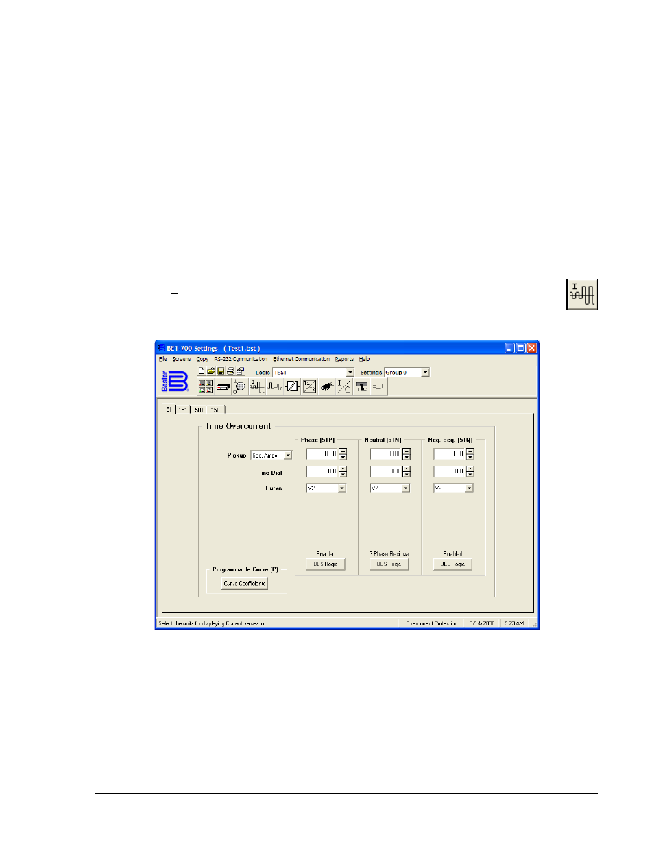
Pull down the Screens menu and select Overcurrent Protection or click on the Overcurrent
Protection icon, which is shown at the right margin of this paragraph. This screen has four folder
tabs and the first tab is 51 (Figure 14-12).
Figure 14-12. Overcurrent Protection Screen, 51 Tab (Time Overcurrent)
51 and 151 (Time Overcurrent)
This tab (Figure 14-12) allows you to enter the settings for the time overcurrent elements. BE1-700 relays
have four time overcurrent elements (three with the 51 element and one with the 151 element). The pull
down Pickup menu allows you to select the relative pickup quantity. As the default, BE1-700 relays
measure the current input in secondary amperes. If you want to use primary current, per unit or percent
amperes, you must coordinate the settings in CT & VT Setup and Conversions. Settings for Time Dial and
Curve (time characteristic curve) are conventional settings. If you want to change the characteristic curve
constants, select the Curve Coefficients and a dialog box opens for those entries. Select the BESTlogic
box at the bottom of the Phase (51P) column. The status of the logic is shown above the BESTlogic box.
9376700990 Rev M
BE1-700 BESTCOMS Software
14-11