Figure 4-21. inverse time delay and reset time -26 – Basler Electric BE1-700 User Manual
Page 82
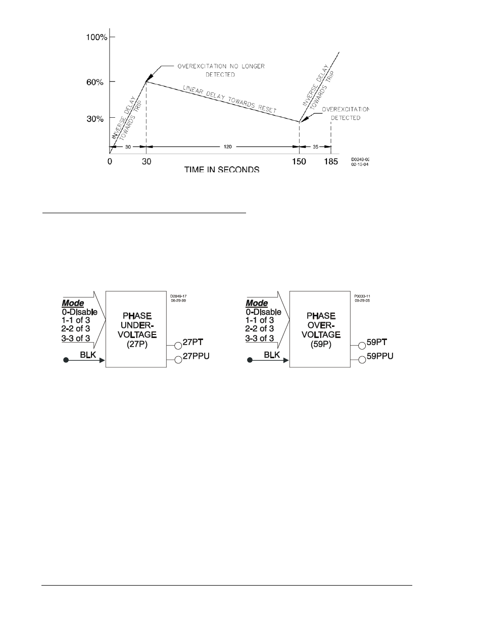
Figure 4-21. Inverse Time Delay and Reset Time
Retrieving Overexcitation Protection Status from the Relay
The status of each logic variable can be determined through the ASCII command interface using the RG-
STAT (report general-status) command. See Section 6, Reporting and Alarm Functions, General Status
Reporting, for more information. The status can also be determined using BESTCOMS Metering screen.
27P/59P - Phase Undervoltage/Overvoltage Protection
Figure 4-22 illustrates the Phase Undervoltage/Overvoltage Logic Blocks. The 127P phase undervoltage
element and the 159P phase overvoltage element are identical in configuration.
Figure 4-22. Phase Undervoltage/Overvoltage Logic Blocks
Each element has two logic outputs: 27PT (Trip) and 27PPU (Pickup). When the monitored voltage
decreases below the undervoltage pickup setting (27P) or increases above the overvoltage pickup setting
(59P), the pickup output becomes TRUE and the element starts timing toward a trip. The trip output
becomes TRUE when the element timer times out. The BLK (Block) input is used to disable protection. A
BESTlogic expression defines how the BLK input functions. When this expression is TRUE, the element
is disabled by forcing the outputs to logic 0 and resetting the timer. This feature functions in a similar way
to the torque control contact of an electromechanical relay.
An element is enabled or disabled by the Mode input. Any one of four modes is possible for the phase
undervoltage and phase overvoltage elements. Selecting Mode 0 disables protection. Mode 1 activates
protection when one of the three phases of voltage decreases below the pickup setting (27P) or increases
above the pickup setting (59P). Mode 2 requires two of the three phases of voltage to be beyond the
pickup setting. Mode 3 requires all three phases of voltage to be beyond the pickup setting. More
information about logic mode selections is provided in the BESTlogic Settings for Phase Undervoltage
and Overvoltage in this section.
The phase undervoltage and overvoltage protective functions each include a timer and three independent
comparators, one for each phase. The 27P/59P functions can be set to monitor VPP or VPN. This is
determined by the 27/59 mode parameter of the phase VT connections setting. For more information on
the VTP setup for PP or PN voltage response, see Section 3, Input and Output Functions, Power System
Inputs, Voltage Measurement.
4-26
BE1-700 Protection and Control
9376700990 Rev M