Basler Electric BE1-700 User Manual
Page 90
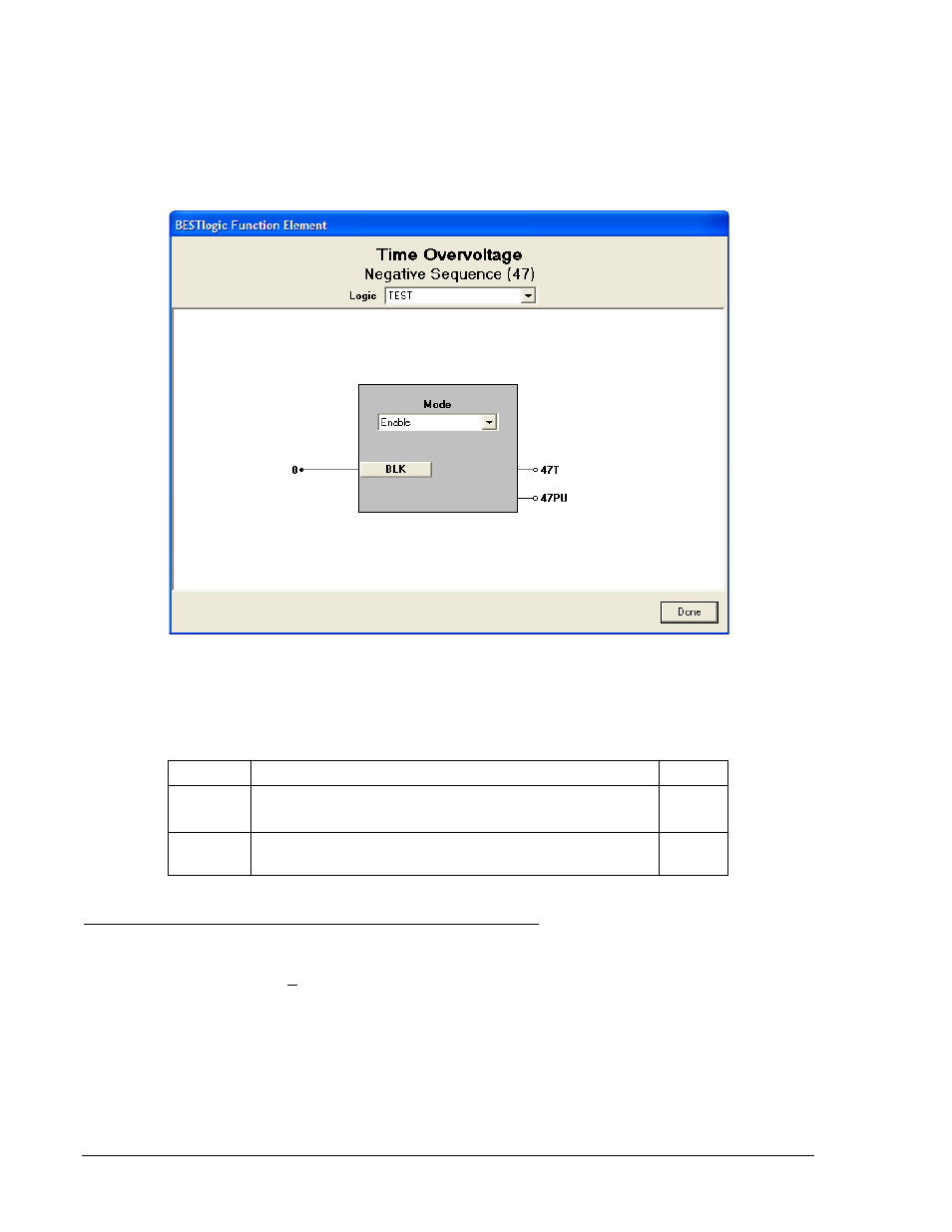
Enable the negative-sequence overvoltage function by selecting its mode of operation from the Mode pull-
down menu. To connect the elements inputs, select the button for the corresponding input in the
BESTlogic Function Element screen. The BESTlogic Expression Builder screen will open. Select the
expression type to be used. Then, select the BESTlogic variable, or series of variables to be connected to
the input. Select Save when finished to return to the BESTlogic Function Element screen. For more
details on the BESTlogic Expression Builder, see Section 7, BESTlogic Programmable Logic. Select
Done when the settings have been completely edited.
Figure 4-29. BESTlogic Function Element Screen, Negative Sequence (47)
Figure 4-21 summarizes the BESTlogic settings for Negative-Sequence Overvoltage Protection.
Table 4-21. BESTlogic Settings for Negative-Sequence Overvoltage Protection
Function
Range/Purpose
Default
Mode
0 = Disabled
1 = Enabled
0
BLK
Logic expression that disables function when TRUE. A
setting of 0 disables blocking.
0
Operating Settings for Negative-Sequence Overvoltage Protection
Operating settings are made using BESTCOMS. Figure 4-30 illustrates the BESTCOMS screen used to
select operational settings for the negative-sequence overvoltage element. To open the screen select
Voltage Protection from the Screens pull-down menu and then select the 47 tab. Alternately, settings
maybe made using the S<g>-47 ASCII command or through the HMI interface using Screen 5.x.5.1
where x represents 1 (Setting Group 0) or 2 (Setting Group 1).
Beside the Logic pull-down menu is a pull-down menu labeled Settings. The Settings menu is used to
select the setting group that the elements settings apply to.
The default unit of measure for the Pickup setting is secondary volts. Primary volts (Pri Volts), per unit
volts (Per U Volts), and percent volts (% Volts) can also be selected as the pickup setting unit of measure.
The unit of measure for the Time setting that represents the element's time delay defaults to milliseconds.
It is also selectable for seconds, minutes, and cycles.
4-34
BE1-700 Protection and Control
9376700990 Rev M