The 46 curve, The 46 curve characteristics, Ik t – Basler Electric BE1-700 User Manual
Page 420
coordination is tight, it is recommended that you retrofit your circuits with Basler Electric electronic relays
to ensure high timing accuracy.
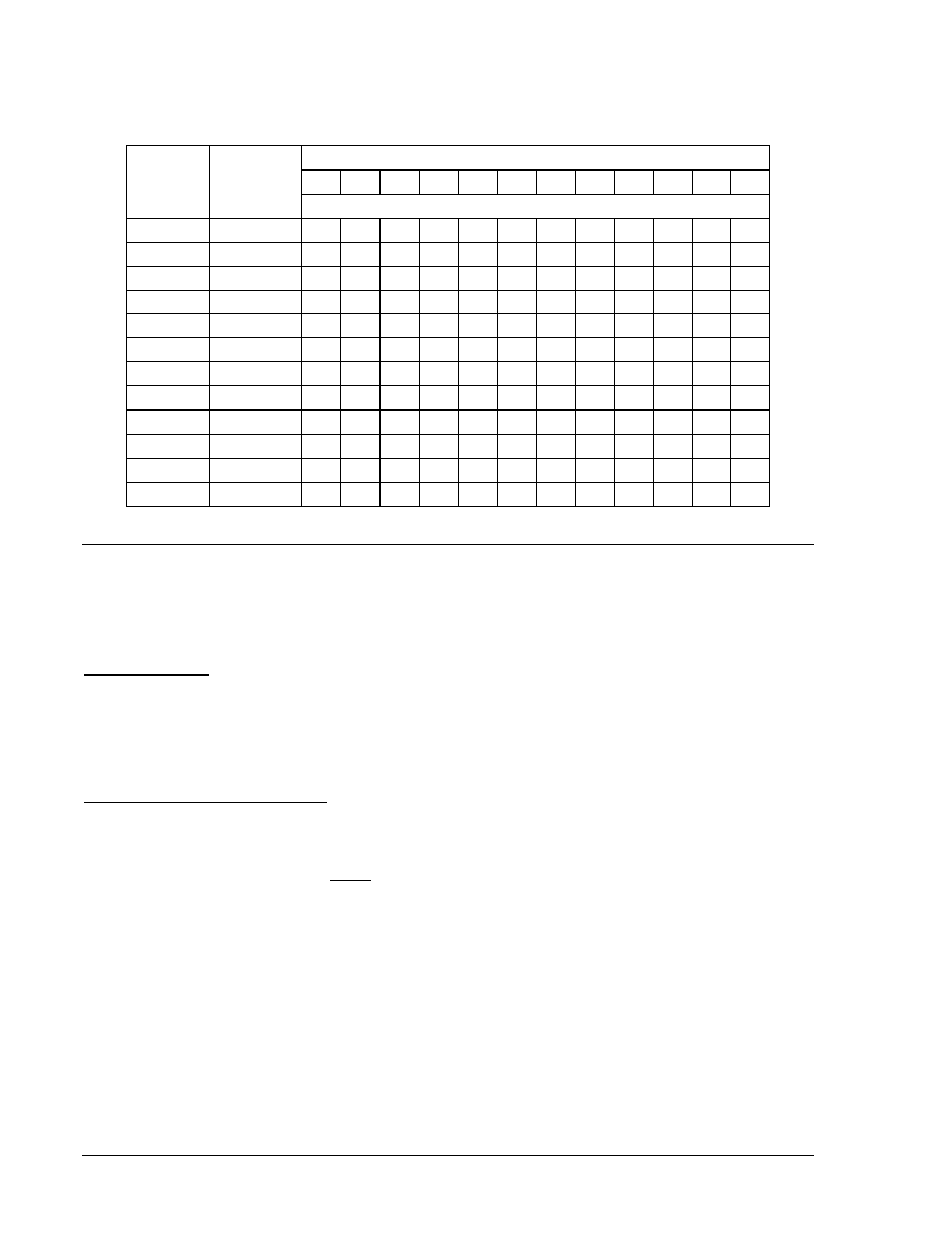
Table A-3. Time Dial Setting Cross-Reference
Curve
Equivalent
To
Electromechanical Relay Time Dial Setting
0.5
1.0
2.0
3.0
4.0
5.0
6.0
7.0
8.0
9.0 10.0 11.0
Basler Electric Equivalent Time Dial Setting
S, S1
ABB CO-2
0.3
0.8
1.7
2.4
3.4
4.2
5.0
5.8
6.7
7.7
8.6
9.7
L, L1
ABB CO-5
0.4
0.8
1.5
2.3
3.3
4.2
5.0
6.0
7.0
7.8
8.8
9.9
D
ABB CO-6
0.5
1.1
2.0
2.9
3.7
4.5
5.0
5.9
7.2
8.0
8.9 10.1
M
ABB CO-7
0.4
0.8
1.7
2.5
3.3
4.3
5.3
6.1
7.0
8.0
9.0
9.8
I, I1
ABB CO-8
0.3
0.7
1.5
2.3
3.2
4.0
5.0
5.8
6.8
7.6
8.7 10.0
V, V1
ABB CO-9
0.3
0.7
1.4
2.1
3.0
3.9
4.8
5.7
6.7
7.8
8.7
9.6
E, E1
ABB CO-11
0.3
0.7
1.5
2.4
3.2
4.2
5.0
5.7
6.6
7.8
8.5 10.3
I2
GE IAC-51
0.6
1.0
1.9
2.7
3.7
4.8
5.7
6.8
8.0
9.3 10.6 N/A
V2
GE IAC-53
0.4
0.8
1.6
2.4
3.4
4.3
5.1
6.3
7.2
8.4
9.6
N/A
S2
GE IAC-55
0.2
1.0
2.0
3.1
4.0
4.9
6.1
7.2
8.1
8.9
9.8
N/A
L2
GE IAC-66
0.4
0.9
1.8
2.7
3.9
4.9
6.3
7.2
8.5
9.7 10.9 N/A
E2
GE IAC-77
0.5
1.0
1.9
2.7
3.5
4.3
5.2
6.2
7.4
8.2
9.9
N/A
THE 46 CURVE
The 46 curve (Figure A-17) is a special curve designed to emulate the (I
2
)
2
t withstand ratings of
generators using what is frequently referred to as the generator K factor.
The 46 Curve Characteristics
46 Pickup Current
Generators have a maximum continuous rating for negative sequence current. This is typically expressed
as a percent of stator rating. When using the 46 curve, the user should convert the continuous I
2
rating
data to actual secondary current at the relay. This value (plus some margin, if appropriate) should be
entered as the pickup setting. For example, if a generator’s rated full-load current is 5 amperes, a pu
setting of 0.5 A would allow 10% continuous I
2
.
46 Time Dial (= Generator K factor)
The amount of time that a generator can withstand a given level of unbalance is defined by Equation A-3.
( )
2
2
I
K
t
=
Equation A-3
The K factor gives the time that a generator can withstand 1 per unit negative sequence current. For
example, with a K factor of 20, since (I
2
)
2
becomes 1 at 1 per unit of current, the generator can withstand
the condition for 20 seconds. Typical values for generator K factors are in the 2 to 40 range. The relay
uses the “nominal current” setting of the relay (front panel Screen 6.3.7 or via the SG-NOM command) to
determine what corresponds to 1 per unit current in the generator.
When curve 46 is selected, the relay changes the range of the allowed time dial to 1 to 99 (instead of the
time dial range of 0.1 to 9.9 for all the other curves). The user should enter the “K” factor of the generator
into the time dial field.
A-4
BE1-700 Time Overcurrent Characteristic Curves
9376700990 Rev M