Table 13-46. 27x uv inhibit pickup settings -30 – Basler Electric BE1-700 User Manual
Page 326
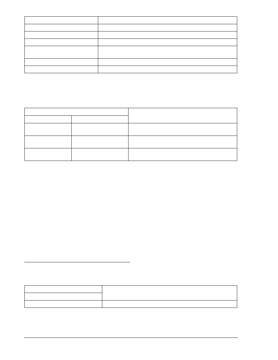
Command
Purpose
SL-159X=2,0
Enables 159X, disables blocking.
SL-VO1=27XT+59XT
Enables OUT1 to close for 27X and 59X trip.
SL-VO2=159XT
Enables OUT2 to close for 159X trip.
SG-TRIG=27XT+59XT+159XT,
27XPU+59XPU+159XPU,0
Enable 27XT, 59XT, or 159XT to log and trigger fault recording.
SG-TARG=27/59/159
Enables 27X, 59X, and 159X targets.
EXIT;Y
Exit and save settings.
Step 2: Using Table 13-45 as a guide, transmit the first row of setting commands (highest 27X PU,
highest 59XPU/159XPU) to the relay.
Table 13-45. 27X and 59X/159X Pickup Settings (3V0)
Pickup Settings
Purpose
Undervoltage
Overvoltage
S0-27X=50,50ms,0
S0-59X/159X=60,50ms
Sets 27X PU at 50 V, 59X/159X at 60 V, TD at min,
UV Inhibit disabled.
S0-27X=20,50ms,0
S0-59X/159X=30,50ms
Sets 27X PU at 20 V, 59X/159X at 30 V, TD at min,
UV Inhibit disabled.
S0-27X=5,50ms,0
S0-59X/159X=10,50ms
Sets 27X PU at 5 V, 59X/159X at 10 V, TD at min,
UV Inhibit disabled.
Step 3: Prepare to monitor the 59X/159X function operation. Operation can be verified by monitoring
OUT1 (OUT2 for 159X).
Step 4: Connect and apply a single-phase, 55 Vac voltage source to Terminals C13 (polarity) and C16
(non-polarity). Refer to Figure 12-4 for terminal locations.
Step 5: Slowly decrease the voltage until OUT1 closes. Pickup should occur within
±2 percent or 1 volt
of the 27X pickup setting. Slowly increase the voltage until OUT1 opens. Dropout should occur
between 102% and 103% of the actual pickup value. Verify the 27N target on the HMI and
reset.
Step 6: Continue increasing the voltage until OUT1 closes. Pickup should occur within
±2 percent or 1
volt of the pickup setting. Slowly reduce the voltage until OUT1 opens. Dropout should occur
between 97% and 98% of the actual pickup value. Verify the 59N target on the HMI.
Step 7: Verify the pickup and dropout accuracy of the middle and upper pickup settings in Table 13-45.
Step 8: (Optional.) Repeat Steps 2 through 7 for the B-phase and C-phase voltage inputs.
Step 9: (Optional.) Repeat Steps 2 through 8 for Setting Group 1.
27X Auxiliary Undervoltage Inhibit Pickup Test (3V0)
Step 1: Using Table 13-46 as a guide, transmit the setting commands to the relay.
Table 13-46. 27X UV Inhibit Pickup Settings
Phase Inhibit Pickup Settings
Purpose
Undervoltage
S0-27X=96,50ms,50
Sets 27X PU at 96 V, Time Dial at minimum, UV Inhibit at 50V.
Step 2: Using the same test connections as Step 4 above, slowly decrease the A-phase voltage until
OUT1 closes. Pickup should occur within
±2 percent or 1 volt of the 27X pickup setting.
13-30
BE1-700 Testing and Maintenance
9376700990 Rev M