Logic timers, 62 - general purpose logic timers, Logic timers -43 – Basler Electric BE1-700 User Manual
Page 99: 62 - general purpose logic timers -43, Mode 1, pu/do (pickup/dropout timer) -43, Mode 2, one-shot nonretriggerable timer -43
LOGIC TIMERS
62 - General Purpose Logic Timers
BE1-700 relays provide two general-purpose logic timers, which are extremely versatile. Each can be set
for one of five modes of operation to emulate virtually any type of timer. Each function block has one
output (62 or 162) that is asserted when the timing criteria has been met according to the BESTlogic
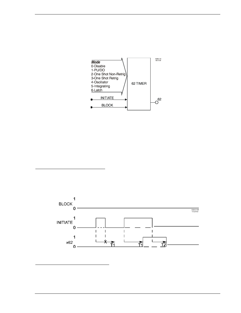
mode setting. Figure 4-37 shows the 62 function block as an example. Each mode of operation is
described in detail in the following paragraphs.
Figure 4-37. General Purpose Logic Timers Logic Block
An INITIATE logic input is provided to start the timing sequence.
A BLOCK logic input is provided to block operation of the timer. When this expression is TRUE, the
function is disabled.
Each timer has a T1 time setting and a T2 time setting. The functioning of these settings is dependent
upon the type of timer as specified by the mode setting in BESTlogic.
If the target is enabled for the function block, the target reporting function will record a target when the
timer output is TRUE and the fault recording function trip logic expression is TRUE. See Section 6,
Reporting and Alarm Functions, Fault Reporting, for more details on the target reporting function.
Mode 1, PU/DO (Pickup/Dropout Timer)
The output will change to logic TRUE if the INITIATE input expression is TRUE for the duration of
PICKUP time delay setting T1. See Figure 4-38. If the initiate expression toggles to FALSE before time
T1, the T1 timer is reset. Once the output of the timer toggles to TRUE, the INITIATE input expression
must be FALSE for the duration of DROPOUT time delay setting T2. If the INITIATE input expression
toggles to TRUE before time T2, the output stays TRUE and the T2 timer is reset.
Figure 4-38. Mode 1, PU/DO (Pickup/Dropout Timer)
Mode 2, One-Shot Nonretriggerable Timer
The one-shot nonretriggerable timer starts its timing sequence when the INITIATE input expression
changes from FALSE to TRUE. See Figure 4-39. The timer will time for DELAY time T1 and then the
output will toggle to TRUE for DURATION time T2. Additional initiate input expression changes of state
are ignored until the timing sequence has been completed. If the duration time (T2) is set to 0, this timer
will not function. The timer will return to FALSE if the BLOCK input becomes TRUE.
9376700990 Rev M
BE1-700 Protection and Control
4-43