Basler Electric BE1-700 User Manual
Page 119
the ground trip output of the relay. Instead, a virtual switch can be used to reduce costs with the added
benefit of being able to operate the switch both locally through the HMI and remotely from a substation
computer or through a modem connection to a remote operator's console.
The state of the switches can be controlled from the optional HMI or ASCII command interface. Control
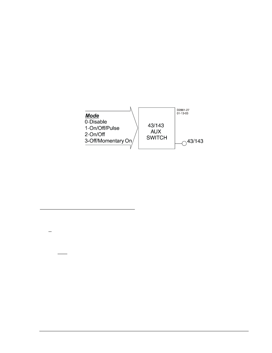
actions can be set by the BESTlogic mode setting. When set for On/Off/Pulse, each switch can be
controlled to open (logic 0), close (logic 1), or pulse such that the output toggles from its current state to
the opposite state and then returns. Additional modes allow the switch operation to be restricted. In
On/Off, the switch emulates a two-position selector switch, and only open and close commands are
accepted. In Off/Momentary On, a momentary close, spring-return switch is emulated and only the pulse
command is accepted. Because switch status information is saved in nonvolatile memory, the relay
powers up with the switches in the same state as when the relay was powered down.
Each virtual selector switch element (see Figure 4-62) has one output: 43 or 143. The output is TRUE
when the switch is in the closed state; the output is FALSE when the switch is the open state. Since both
the output and the inverse of the output of these switches can be used as many times as desired in your
programmable logic, they can emulate a switch with as many normally open and normally closed decks
as desired.
Figure 4-62. Virtual Selector Switches Logic Block
User specified labels could be assigned to each virtual switch and to both states of each switch. In the
previous ground cutoff switch example, you might enable one of the switches in BESTlogic as Mode 2,
ON/OFF and connect the output of that switch to the blocking input of the 59x protection element. This
would disable the ground overvoltage protection when the switch is closed (logic 1) and enable it when
the switch is open (logic 0). For the application, you might set the switch label to be 59N_CUTOFF (10
character maximum). The closed position on the switch might be labeled DISABLD (7 character
maximum) and the open position might be labeled NORMAL. Section 7, BESTlogic Programmable Logic,
has more details about setting user programmable names for programmable logic variables.
BESTlogic Settings for Virtual Selector Switches
BESTlogic settings are made from the BESTlogic Function Element screen in BESTCOMS. Figure 4-63
illustrates the BESTCOMS screen used to select BESTlogic settings for the Virtual Switch element. To
open the BESTlogic Function Element screen for the Virtual Switch element, select Virtual Switches from
the Screens pull-down menu. Then select the BESTlogic button for the virtual switch to be edited.
Alternately, settings may be made using SL-43 or SL-143 ASCII commands.
At the top center of the BESTlogic Function Element screen is a pull-down menu labeled Logic. This
menu allows viewing of the BESTlogic settings for each preprogrammed logic scheme. A custom logic
scheme must be created and selected in the Logic pull-down menu at the top of the screen before
BESTlogic settings can be changed. See Section 7, BESTlogic Programmable Logic.
Enable the Virtual Switch function by selecting its mode of operation from the Mode pull-down menu.
Select Done when the settings have been completely edited.
9376700990 Rev M
BE1-700 Protection and Control
4-63