Table 13-88. x62 mode 3 test commands -49, N table 13-88 – Basler Electric BE1-700 User Manual
Page 345
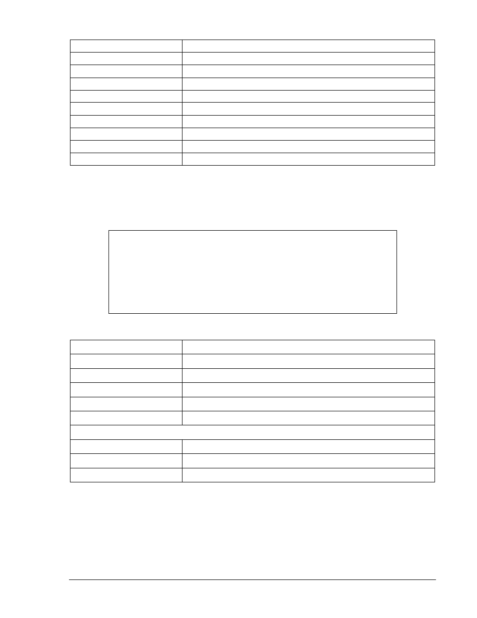
Table 13-88. x62 Mode 3 Test Commands
Command
Purpose
A=
Gains write access.
SL-N=NONE
Zero out custom logic settings. Overwrite with LOGIC=NONE settings.
Y
Confirm overwrite.
SL-N=T62
Sets T62 as custom logic name.
SL-62=3,43,0
Enables 62 one-shot, retriggerable mode, 43 initiate, no blocking.
SL-43=3
Enables 43 Switch momentary pulse mode.
SN-43=62_INI,INI,NORMAL
Name Switch 43 to make SER easier to read.
S0-62=15s,20s
Sets 62 delay at 15 seconds. Sets 62 dropout at 20 seconds.
EXIT;Y
Exit and save settings.
Step 2: Transmit the commands of Table 13-89 to the relay. These commands supply the 62 Timer with
a momentary initiate input by pulsing the 43 Switch from FALSE to TRUE and then back to
FALSE. You may view the state changes of the 43 Switch at Screen 1.5.4 of the front panel
HMI.
Table 13-89. x62 Mode 3 Timer Initiate Commands
Command
Purpose
A=
Gains write access.
CS-43=P
Selects 43 for pulse F-T-F operation.
CO-43=P
Executes 43 pulse F-T-F operation.
CS-43=P
Selects 43 for pulse F-T-F operation.
CO-43=P
Executes 43 pulse F-T-F operation.
Wait at least 15 seconds (but no longer than 35 seconds) to execute next commands.
CS-43=P
Selects 43 for pulse F-T-F operation.
CO-43=P
Executes 43 pulse F-T-F operation.
EXIT
Exit select and operate mode.
Step 3: Use the RS-LGC command to obtain an SER report and verify that the following actions were
logged. These events are illustrated in the timing diagram of Figure 13-3.
Approximately 15 seconds after the second 43 FALSE to TRUE initiate signal, the 62 Timer
output went TRUE. The timer output went FALSE when the third FALSE to TRUE initiate signal
forced the 62 Timer (T1) to restart.
NOTE
The 43 Switch action is performed three times in this test. To illustrate the action
of the timer mode, the second 43 Switch action should be executed as quickly as
possible (within the 15 second duration of the pickup time delay). Perform the
third 43 Switch action after at least 15 seconds (the pickup timer setting) have
elapsed but before the 20 second dropout time delay expires. This will illustrate
the action of the timer mode. The time delay settings may be increased if
difficulty is encountered with repeating the 43 Switch actions.
9376700990 Rev M
BE1-700 Testing and Maintenance
13-49